+7 747 505 1212

HEMI ANALOG Adapter

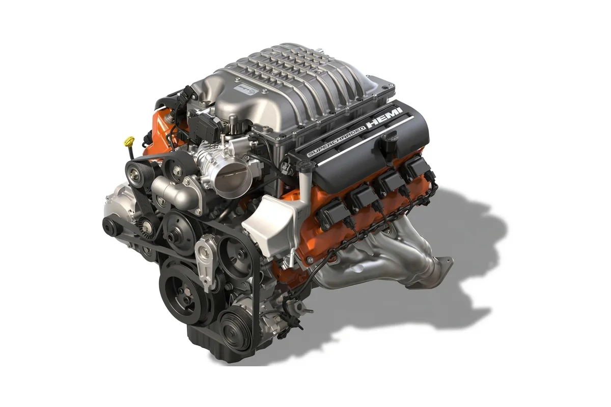
Adapter for swapping a Chrysler / Dodge / Jeep HEMI 5.7 or SRT 6.1 engine (2005–2010) with a 545RFE or Mercedes NAG1 transmission into a vehicle with an analog instrument cluster — GAZelle, Nissan Patrol, Mitsubishi Delica, Pajero 2, L200 and others.

It gives the engine and transmission everything they need over the CAN bus to run properly, and drives the stock cluster: speedometer, tachometer and the CHECK ENGINE, oil pressure, charging and reverse lamps.

Set up in the GoSwap configurator from a phone over a USB cable: gear ratios, wheel circumference, where speed comes from — the transmission output shaft or a separate sensor, fine-tuning of the speedometer and tachometer.

With NAG1, the configurator reads the gear ratios and wheel circumference from the transmission control unit by itself.

Version 3.3 · 06.10.2026

GoSwap Cfg app

The adapter is set up from a phone over a USB Type-C cable. The app shows what the adapter receives and sends, and updates its firmware. Point your phone camera at the code to open the app page with the download link.

goswap.kz/en/cfg/

GoSwap · goswap.kz/catalog/hemi-analog/en/ · +7 747 505 1212 1 / 9

Connection

13 +IGN

Red

+IGN — +12 V from the ignition switch — positive with the ignition on

1 GND

Black

GND — chassis ground

3 CAN1 L

White

CAN L — to CAN L of the HEMI engine control unit

15 CAN1 H

Green

CAN H — to CAN H of the HEMI engine control unit

5 PWM1[—]

Gray

SPD — to the speedometer wire of the instrument cluster

Low-side output. If needed: if the stock speedometer runs from its own sensor — for example, on a Nissan Patrol from the transfer case — SPD is not connected.

6 PWM2[—]

Yellow

TACH — to the tachometer wire of the instrument cluster

Low-side output.

7 OUT1[—]

Orange

CHECK — to the CHECK ENGINE lamp of the cluster

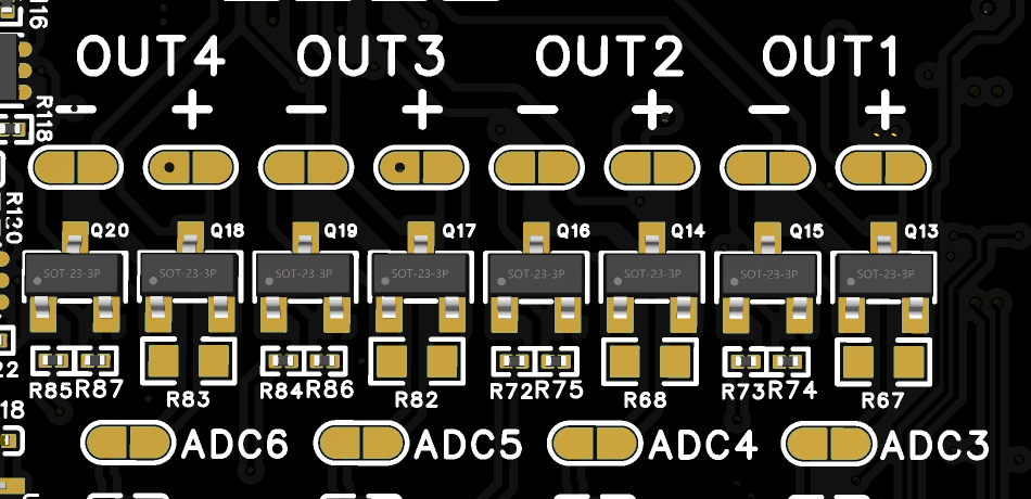
Low-side output — switches to ground. Output polarity can be changed with a jumper (sheet 4).

8 OUT2[—]

Gray

OIL — to the oil pressure lamp of the cluster

Low-side output — switches to ground. Output polarity can be changed with a jumper (sheet 4).

9 OUT3[—]

Light gray

GEN — to the charge lamp of the cluster

No need to connect the alternator. Low-side output — switches to ground. Output polarity can be changed with a jumper (sheet 4).

10 OUT4[—]

Pink

R — to the reverse circuit (lights, camera)

Connect through a relay!

Low-side output — switches to ground. Output polarity can be changed with a jumper (sheet 4).

11 CAPT[+]

Light gray

SPD IN — to the speed sensor on the transmission output shaft

Optional: connected only if speed is taken from a separate sensor rather than over CAN. Active-high input. The input is enabled with the CAPT jumper (sheet 4).

12 GND

Brown

GND — speed sensor ground

Optional: connected only together with a separate speed sensor SPD IN [11].

[—] — output switches to ground · [+] — input triggers from +12 V

Not used: 2, 4, 14, 16–24.

GoSwap · goswap.kz/catalog/hemi-analog/en/ · +7 747 505 1212 2 / 9

Connection order

  1. 1Connect ground GND [1] to the chassis and power +IGN [13] to +12 V from the ignition switch.
  2. 2Connect the engine bus: CAN H [15] and CAN L [3] to CAN H and CAN L of the HEMI engine control unit.
  3. 3Connect the instrument cluster: speedometer SPD [5] — if needed, tachometer TACH [6], lamps CHECK [7], OIL [8] and GEN [9]. The speedometer and tachometer outputs are a square-wave signal switched to ground. If your cluster does not accept it, external components may be needed: resistors and capacitors.
  4. 4Reverse R [10] — only through a relay.
  5. 5Speed sensor — only for the NAG1 transmission, if speed is taken from a separate sensor; it is mounted on the transmission output shaft, with all-wheel drive — before the transfer case. A 3-wire Hall sensor, for example Bremi 600/41: signal to SPD IN [11], ground to GND [12], power — +12 V from the ignition switch; a 10 kΩ resistor between the sensor power and signal.
GoSwap · goswap.kz/catalog/hemi-analog/en/ · +7 747 505 1212 3 / 9

Jumpers

OUT jumpers

From the factory all four outputs are soldered low-side: CHECK [7], OIL [8], GEN [9] and R [10] switch to ground. Resolder an output to high-side only if your lamp or relay is switched by positive.

Do not solder both jumpers on the same channel!

CAPT / +5V jumper

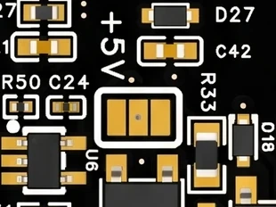
From the factory the jumper is in the CAPT position: SPD IN [11] is the speed sensor input. No need to change it.

CAN termination jumper

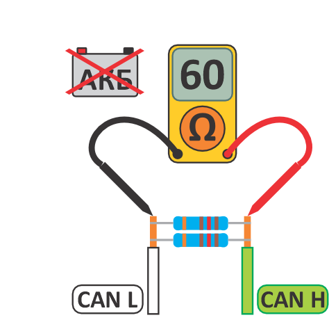
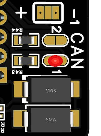
For proper CAN mode operation, the resistance between CAN H and CAN L wires must be 60 Ω. Measure resistance with the adapter connected and battery disconnected. The adapter has a built-in 120 Ω resistor — solder the CAN1 or CAN2 jumper if needed — for the bus the adapter is connected to.

From the factory the terminator is not soldered. The adapter connects to the HEMI engine bus — if the measurement shows 120 Ω, solder the CAN1 jumper.

GoSwap · goswap.kz/catalog/hemi-analog/en/ · +7 747 505 1212 4 / 9

Setup

The adapter is set up in the GoSwap app from a phone over a USB Type-C cable. Changes are sent to the adapter with the “APPLY” button at the bottom of the screen — the number on it shows how many settings have changed.

  1. 1

    Connect the phone.

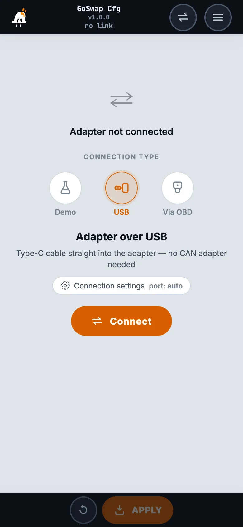
    Install the GoSwap app — app page (goswap.kz/en/cfg/). Turn on the ignition, connect the phone and the adapter with a USB Type-C cable, choose “USB” in the app and tap “Connect”.

    GoSwap app: connection screen, “USB” selected
  2. 2

    Transmission — EGS tab.

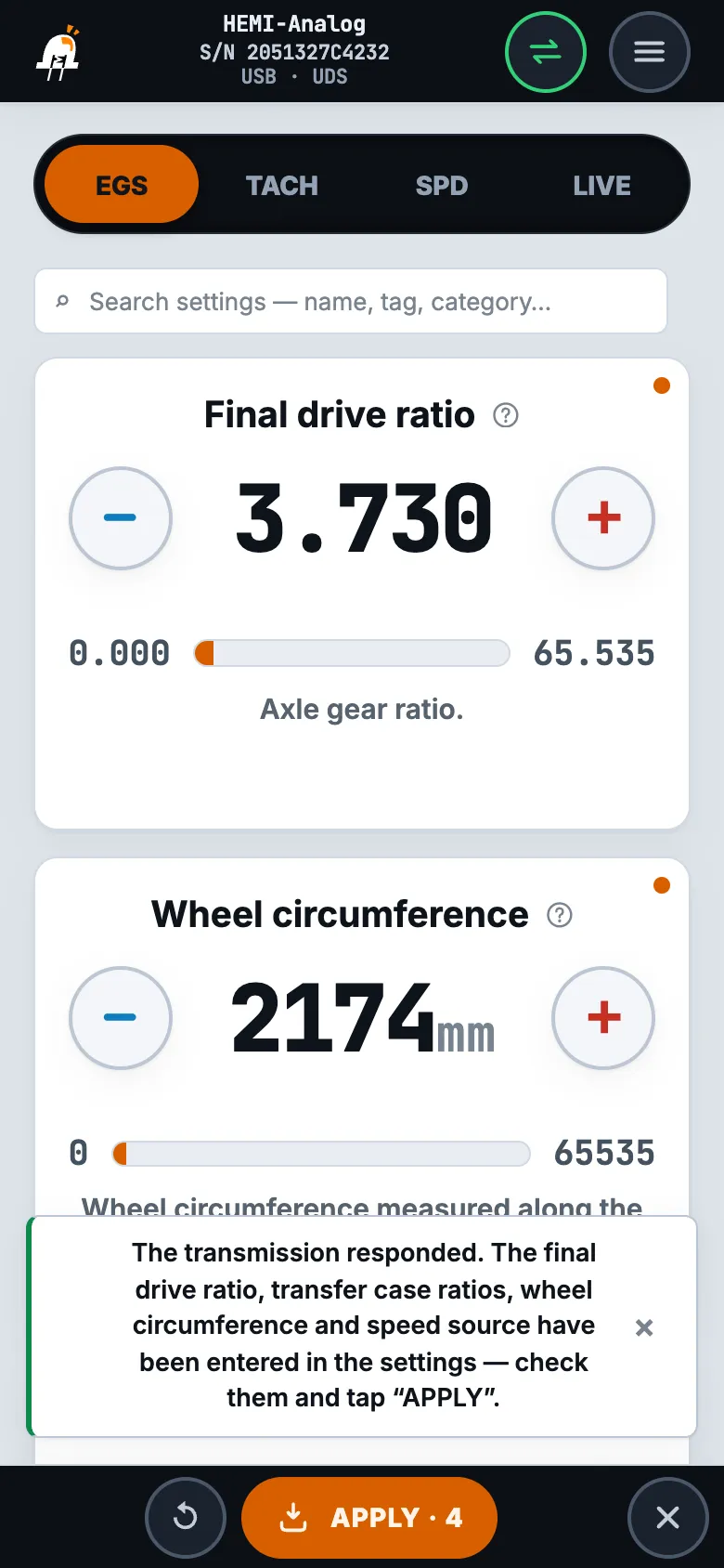
    NAG1 transmission (Mercedes 722.6): at the bottom of the tab tap “Read settings from EGS”. The adapter reads the final drive ratio, wheel circumference, transfer case and speed source from the transmission control unit. New values are marked with an orange dot — check them and tap “APPLY”.

    545RFE transmission: the final drive ratio and wheel circumference can be left as they are, speed source — CAN.

    Speed source ANALOG — only with a separate output shaft sensor on the SPD IN [11] contact: a Hall sensor, 3 wires, 16 pulses per revolution. After “APPLY” the app restarts the adapter by itself.

    EGS tab after “Read settings from EGS”: new values with an orange dot, the “APPLY · 4” button
GoSwap · goswap.kz/catalog/hemi-analog/en/ · +7 747 505 1212 5 / 9

Setup

  1. 3

    Tachometer — TACH tab.

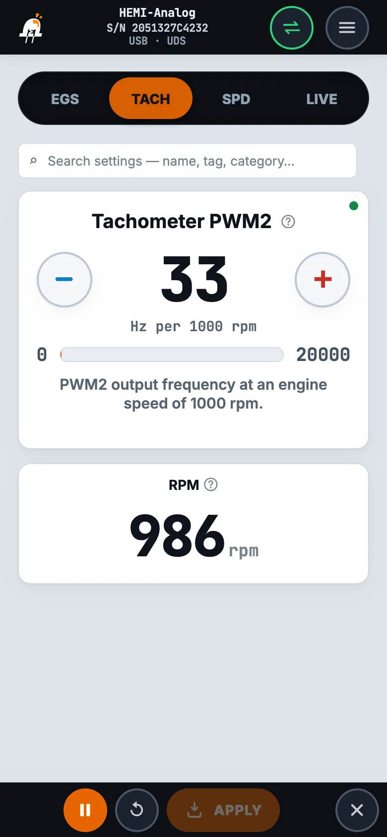
    Start with a typical value: 33 for the cluster of a 4- or 8-cylinder car, 50 for a 6-cylinder one. Tap ▶ at the bottom of the screen — the “RPM” tile shows the engine speed. If the needle reads lower — “+”, higher — “−”, then “APPLY”.

    TACH tab: the “Tachometer PWM2” setting and the “RPM” tile with live engine speed
  2. 4

    Speedometer — SPD tab.

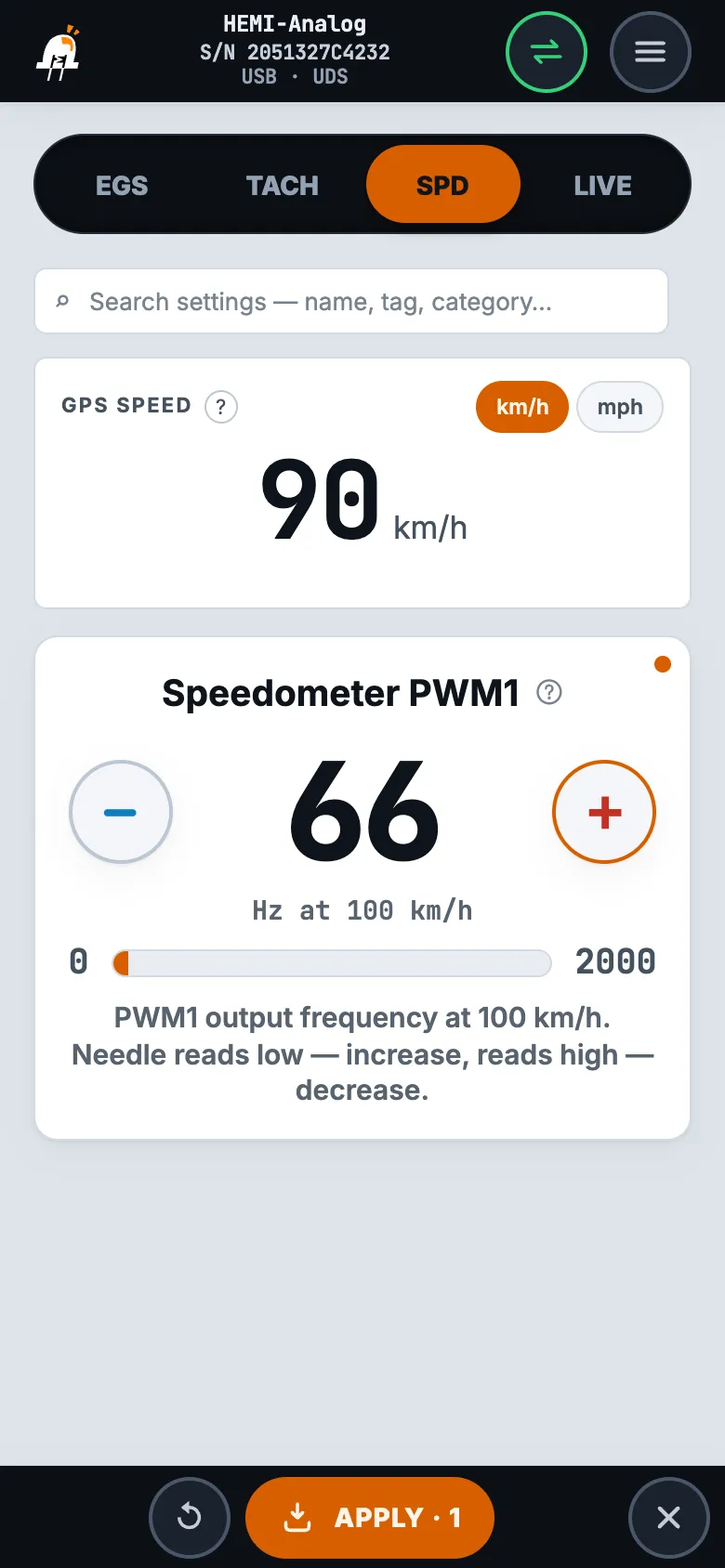
    Only while driving: accelerate to a steady speed, 80–100 km/h, and compare the needle with the “GPS speed” tile above the setting — this is the speed from the phone's GPS. If the needle reads lower, tap “+”, higher — “−”, then “APPLY” and compare again.

    If the cluster speedometer runs from its own sensor and SPD [5] is not connected — skip this step.

    SPD tab: the “GPS speed” tile above the “Speedometer PWM1” setting, a changed value and the “APPLY · 1” button
GoSwap · goswap.kz/catalog/hemi-analog/en/ · +7 747 505 1212 6 / 9

Setup

  1. 5

    Check — LIVE tab.

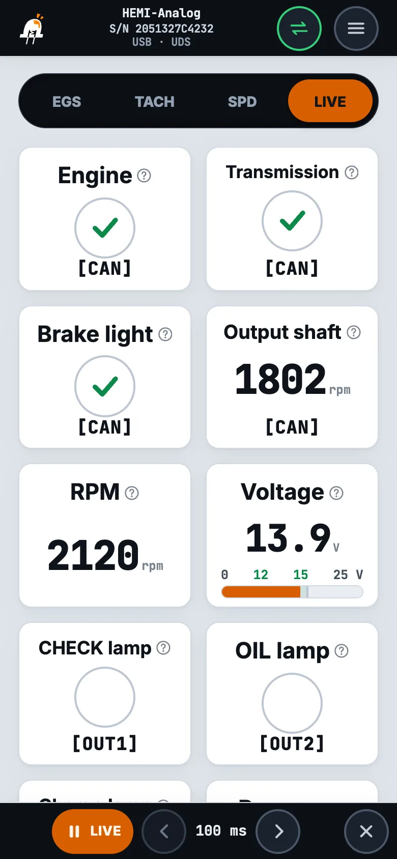
    The tiles show what the adapter receives and sends right now:

    • “Engine” and “Transmission” — a check mark: the adapter is talking to the units over CAN. A cross — check the bus: CAN H [15] and CAN L [3] must not be swapped, resistance between them with the battery disconnected — 60 Ω.
    • “Brake light” — lights up when the brake pedal is pressed; the signal comes over CAN.
    • “RPM” — engine speed from the engine control unit over CAN. If the tachometer shows otherwise — adjust “Tachometer PWM2”, step 3.
    • “Output shaft” — transmission output shaft speed: over CAN from the transmission or from the SPD IN [11] sensor, depending on the selected speed source. Rises with speed while driving.
    • “Voltage” — the voltage at the adapter itself, normally 12–15 V. It also depends on the ground: lower than at the battery — check ground GND [1] and power +IGN [13].
    • “CHECK lamp” and “OIL lamp” — follow the engine control unit signals over CAN; with no connection to the engine both flash. “Charge lamp” — lights up when the vehicle voltage is below 12 V.
    • “Reverse” — turns on when the transmission selector is in R; the signal comes over CAN.
    LIVE tab: connection to the engine and transmission, brake light, output shaft, RPM, vehicle voltage and lamp outputs
GoSwap · goswap.kz/catalog/hemi-analog/en/ · +7 747 505 1212 7 / 9

Questions and answers

Connection and power

The orange LED flashes 10 times, the needles are at zero, the CHECK and OIL lamps flash
No connection to the engine or transmission over CAN. Check that CAN H [15] and CAN L [3] are not swapped; resistance between them with the battery disconnected — 60 Ω (CAN terminator (sheet 4)); power +IGN [13] and ground GND [1]. In the app — the “Engine” and “Transmission” tiles on the LIVE tab.
The charge lamp is on although the alternator is charging
The lamp lights up when the voltage at the adapter itself is below 12 V. Look at “Voltage” on the LIVE tab: lower than at the battery — check the power +IGN [13] and ground GND [1] contacts.

Needles

The speedometer reads high or low
Adjust “Speedometer PWM1” while driving using the “GPS speed” tile — Setup, step 4 (sheets 5–7).
The needle jumps, or goes off the scale and drops to zero
The frequency is higher than the cluster accepts. Lower “Speedometer PWM1” or “Tachometer PWM2” until the needle settles.
The needle does not move, the LED PWM1 or PWM2 on the board is off
There is no pull-up on the cluster side: the cluster does not accept the low-side signal as is. External components are needed — resistors and capacitors.

Lamps

A cluster lamp does not light up
Your cluster lamp is switched by positive, while the adapter output is low-side from the factory. Resolder this output's jumper to [+] — OUT jumpers (sheet 4).

Transmission

NAG1 transmission with a separate speed sensor: the transmission does not recognise the gears
Check the reluctor ring of the output shaft sensor (SPD IN [11]): 16 teeth, evenly spaced, gap to the sensor 1–2 mm; “Pulses per revolution” — 16. With a 12-tooth ring the shaft speed reads a quarter low and the transmission recognises no gear.
GoSwap · goswap.kz/catalog/hemi-analog/en/ · +7 747 505 1212 8 / 9

Board

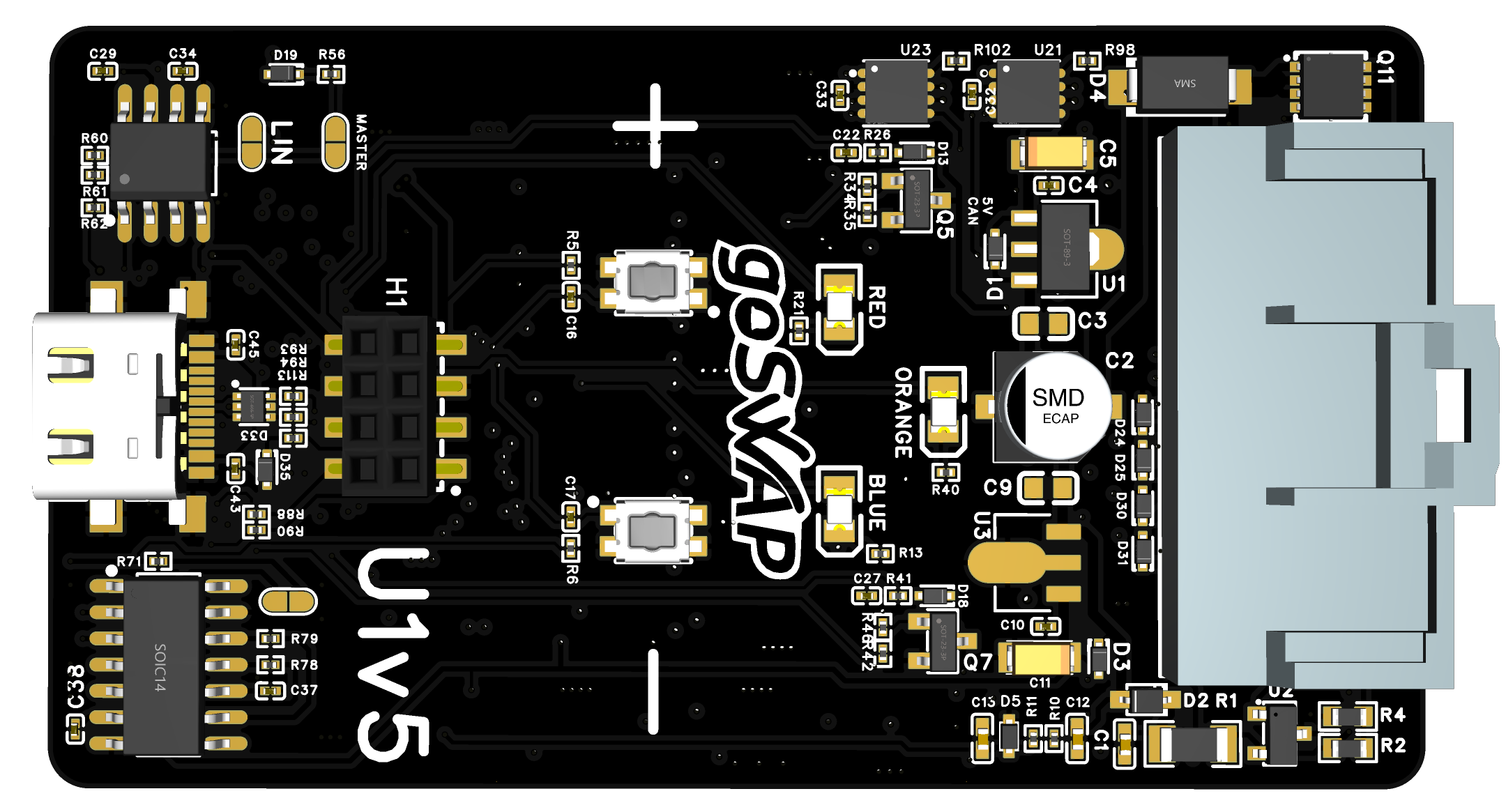
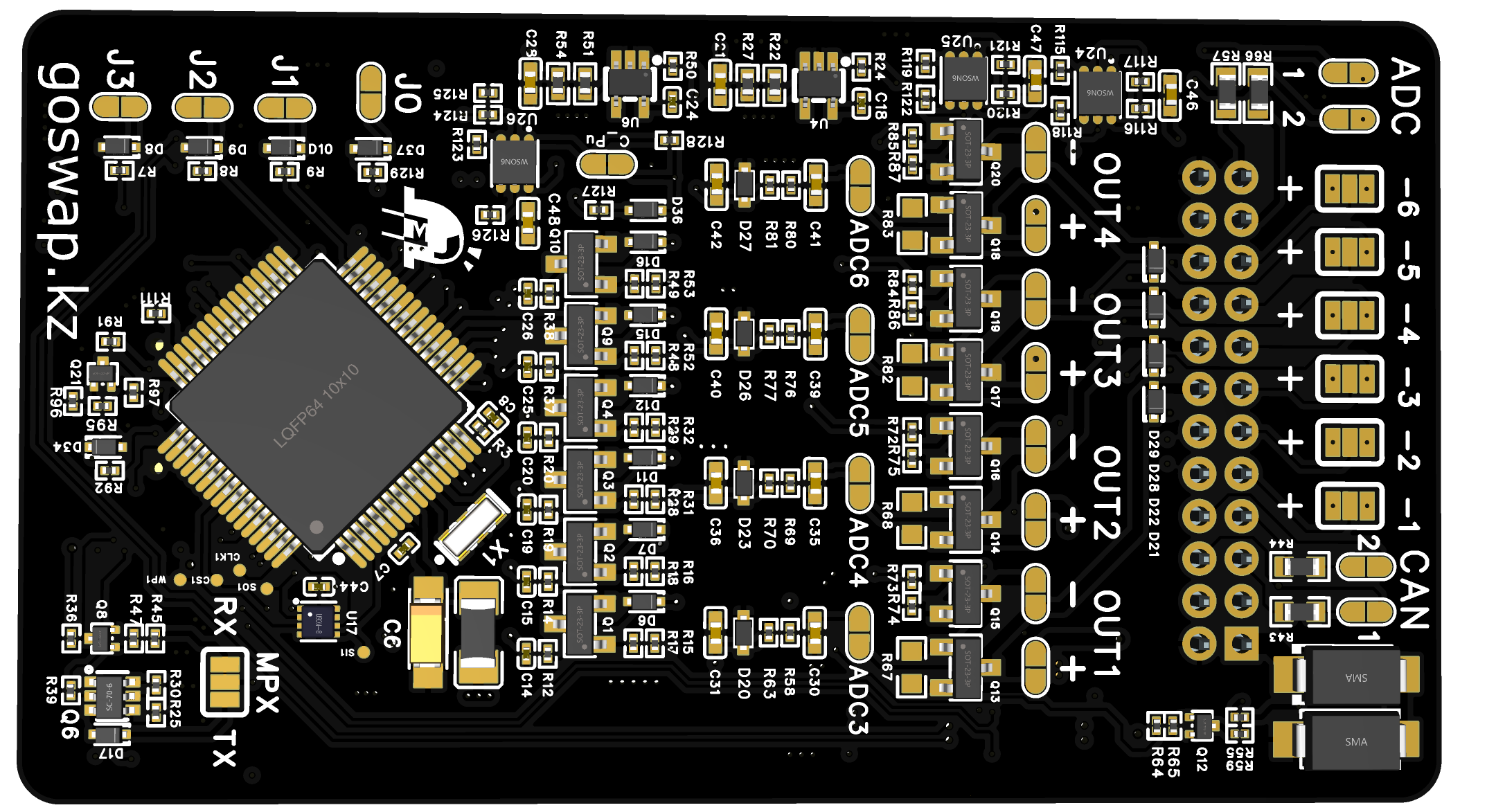
Hover or tap an element to see its function

U1v5 — верх
U1v5 — низ

The app is connected over the USB cable. Blue is on but red is not — the cable is in, the app is not connected.

On — speed is taken from the SPD IN [11] sensor (ANALOG source), off — over CAN. 10 flashes in a row — no connection to the engine or transmission: the CHECK and OIL lamps flash together, the needles are at zero, blue and red are off.

A USB cable is plugged in.

USB Type-C — for a phone with the GoSwap app: setup, firmware update, CAN bus recording for support. No CAN interface is needed.

Polarity of outputs OUT1…OUT4: [+] or [—].

Built-in 120 Ω resistor for the CAN1 or CAN2 bus. When to solder it — see “Jumpers”.

LED PWM1 and LED PWM2 are yellow, on v5.1 boards: they flash with the speedometer (PWM1) and tachometer (PWM2) signal. They light only if there is a pull-up on the cluster side. During a firmware update red, orange and blue light up in turn, in a circle.

Question about wiring? Call or message us on WhatsApp: +7 747 505 1212

GoSwap · goswap.kz/catalog/hemi-analog/en/ · +7 747 505 1212 9 / 9