+7 747 505 1212

U1 v5.x board

The U1 v5 board is the base of GoSwap CAN adapters. Its 24-pin connector carries power, OUT and PWM outputs, six IN inputs, two CAN buses, an MPX bus and ADC inputs. What each pin does in your adapter is set by its firmware, and the polarity of outputs and inputs — by jumpers on the board. All U1 adapters are pin-compatible at the connector, provided all jumpers are soldered correctly.

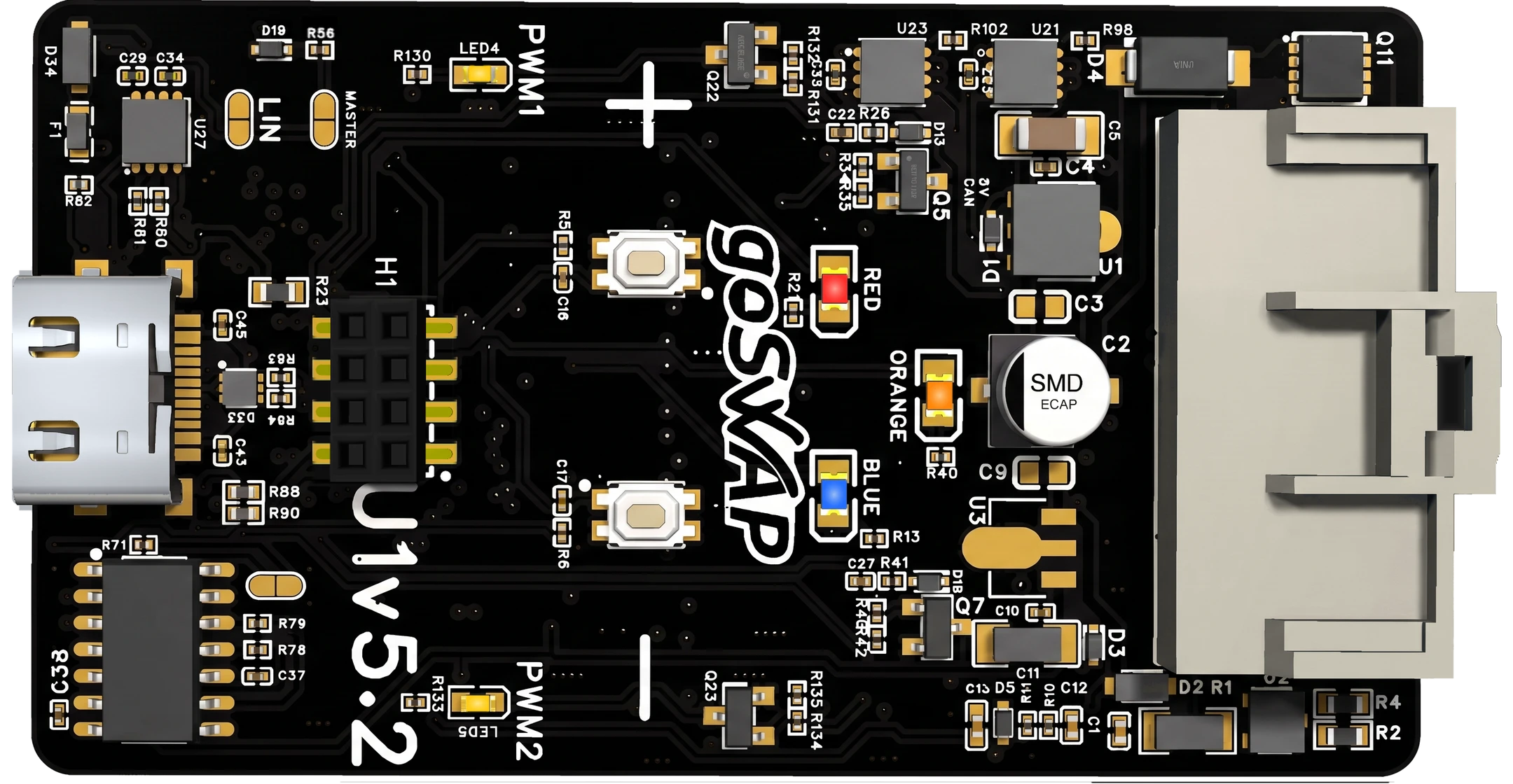
How to tell the revision. The revision is printed in large letters on the top side of the board, next to the logo: U1v5, U1v5.1 or U1v5.2. It is marked on the photo below as “Board revision”.

Connector

121110987654321
GND CAPT OUT4 OUT3 OUT2 OUT1 PWM2 PWM1 CAN2
L
CAN1
L
MPX/
LIN
GND
ADC
1
ADC
2
IN 6 IN 5 IN 4 IN 3 IN 2 IN 1 CAN2
H
CAN1
H
PWR
PWM
+
242322212019181716151413
NameDescription
1 GND
Ground (black wire)
13 +12V
Ignition (red wire)
14 PWR PWM[+]
Power output (positive)
5 PWM1[—] PWM1 IN[—]
6 PWM2[—] PWM2 IN[—]
Signal outputs (negative)PWMx IN — input, active on ground
7 OUT1 OUT1 IN[+]OUT1 ADC
8 OUT2 OUT2 IN[+]OUT2 ADC
9 OUT3 OUT3 IN[+]OUT3 ADC
10 OUT4 OUT4 IN[+]OUT4 ADC
500 mA outputs with configurable polarityOUTx IN — input, active on +12 V · OUTx ADC — voltage measurement 0…14 V
11 CAPT[+] +5V
Signal input (positive)+5V — 5 V sensor supply (from v5.1)
NameDescription
24 ADC1 ADC1 IN
23 ADC2 ADC2 IN
ADC input, max 5 VADCx IN — input, active on + or on ground with pull-up
17 IN1
18 IN2
19 IN3
20 IN4
21 IN5 IN5 CAPT
22 IN6 IN6 CAPT
Digital input with configurable polarityIN5, IN6 CAPT — frequency capture
3 CAN1 L
15 CAN1 H
CAN1 digital bus
4 CAN2 L
16 CAN2 H
CAN2 digital bus
2 MPX
2 K-LINE
2 LIN
MPX, K-Line or LIN bus — one at a time: the adapter firmware sets whichCan also work as an input or an output
12 GND
Sensor ground (brown wire)
GoSwap · goswap.kz/catalog/u1-v5/en/ · +7 747 505 1212 1 / 6

Board — top side

Hover or tap an element to see its function

U1v5.2 — верх
U1v5.2 — низ

Operation indicator. What the colour means depends on the adapter — see its manual.

Same on every adapter: 10 blinks — communication error. Anything else depends on the adapter — see its manual.

Operation indicator. What the colour means depends on the adapter — see its manual.

USB Type-C — updates and setup via the configurator.

Connector for flashing the firmware at the factory.

Manual adapter setup: hold the button while powering on and the adapter enters a setup mode; in that mode a press increases the value. What is set and how is in your adapter’s manual.

Manual adapter setup: hold the button while powering on and the adapter enters a setup mode; in that mode a press decreases the value. What is set and how is in your adapter’s manual.

Only for older adapters without the configurator: reset to factory settings with a jumper at power-on. When it works, all LEDs blink rapidly.

24-pin connector for vehicle wiring: power, CAN, inputs/outputs.

The label on the board is its revision: U1v5, U1v5.1 or U1v5.2.

LED PWM1 blinks together with the PWM1 output. It lights up only when a device is connected to the output: the output switches it to ground. With nothing connected the LED stays off — this is not a fault.

LED PWM2 blinks together with the PWM2 output. It lights up only when a device is connected to the output: the output switches it to ground. With nothing connected the LED stays off — this is not a fault.

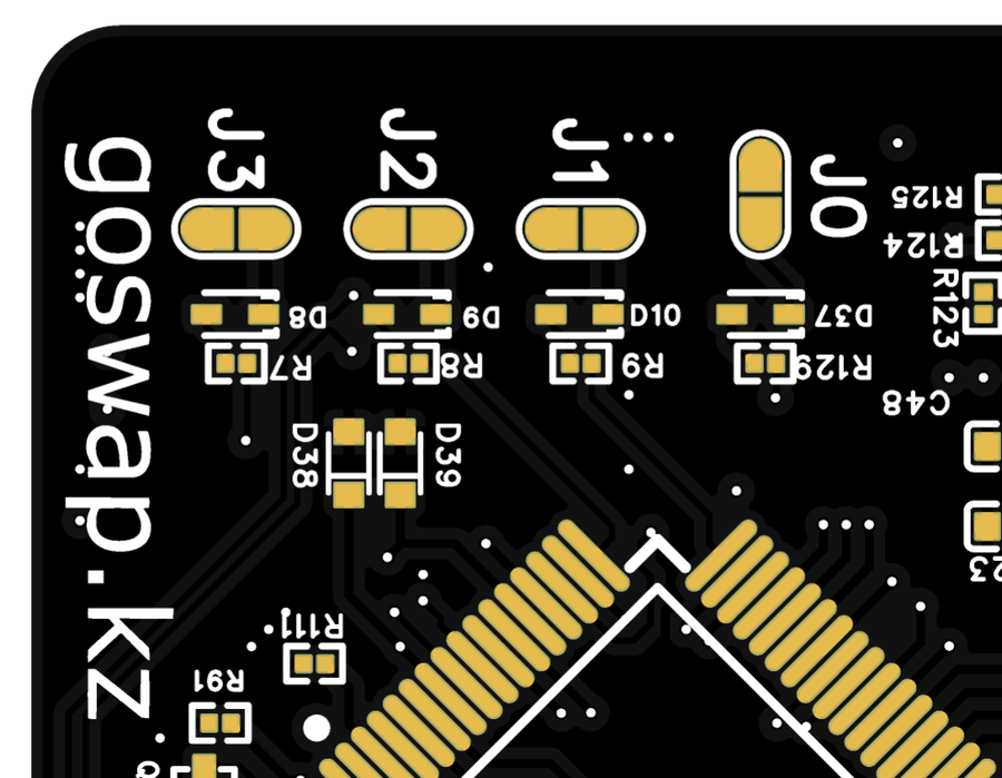
What they switch on is set by the adapter firmware — for example, the fan type. Which ones to solder is in your adapter’s manual.

Polarity of inputs IN1…IN6 — one jumper per input: [+] or [—].

Polarity of outputs OUT1…OUT4: [+] or [—].

Let an OUT1…OUT4 output work as an input that measures 0…14 V. Prepared at the factory for a specific adapter.

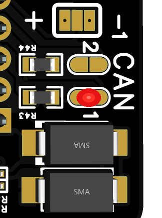
Built-in 120 Ω resistor for the CAN1 or CAN2 bus. When to solder it — see “Jumpers”.

Multiplex bus RX/TX. RX is soldered by default.

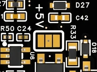
Sets how the CAPT pin (11) works: soldered towards “+5V” — a 5 V output to power sensors (never connect +12 V to the pin then); the other way — a frequency capture input. Soldered at assembly for the specific adapter.

GoSwap · goswap.kz/catalog/u1-v5/en/ · +7 747 505 1212 2 / 6

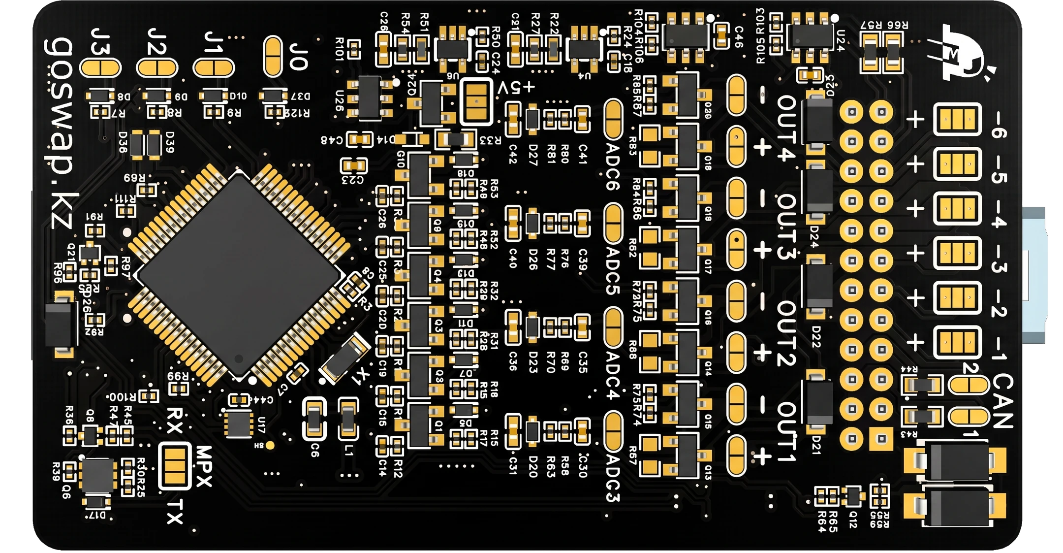
Board — bottom side

Hover or tap an element to see its function

U1v5.2 — верх
U1v5.2 — низ

Operation indicator. What the colour means depends on the adapter — see its manual.

Same on every adapter: 10 blinks — communication error. Anything else depends on the adapter — see its manual.

Operation indicator. What the colour means depends on the adapter — see its manual.

USB Type-C — updates and setup via the configurator.

Connector for flashing the firmware at the factory.

Manual adapter setup: hold the button while powering on and the adapter enters a setup mode; in that mode a press increases the value. What is set and how is in your adapter’s manual.

Manual adapter setup: hold the button while powering on and the adapter enters a setup mode; in that mode a press decreases the value. What is set and how is in your adapter’s manual.

Only for older adapters without the configurator: reset to factory settings with a jumper at power-on. When it works, all LEDs blink rapidly.

24-pin connector for vehicle wiring: power, CAN, inputs/outputs.

The label on the board is its revision: U1v5, U1v5.1 or U1v5.2.

LED PWM1 blinks together with the PWM1 output. It lights up only when a device is connected to the output: the output switches it to ground. With nothing connected the LED stays off — this is not a fault.

LED PWM2 blinks together with the PWM2 output. It lights up only when a device is connected to the output: the output switches it to ground. With nothing connected the LED stays off — this is not a fault.

What they switch on is set by the adapter firmware — for example, the fan type. Which ones to solder is in your adapter’s manual.

Polarity of inputs IN1…IN6 — one jumper per input: [+] or [—].

Polarity of outputs OUT1…OUT4: [+] or [—].

Let an OUT1…OUT4 output work as an input that measures 0…14 V. Prepared at the factory for a specific adapter.

Built-in 120 Ω resistor for the CAN1 or CAN2 bus. When to solder it — see “Jumpers”.

Multiplex bus RX/TX. RX is soldered by default.

Sets how the CAPT pin (11) works: soldered towards “+5V” — a 5 V output to power sensors (never connect +12 V to the pin then); the other way — a frequency capture input. Soldered at assembly for the specific adapter.

GoSwap · goswap.kz/catalog/u1-v5/en/ · +7 747 505 1212 3 / 6

Jumpers

Which jumpers to solder for your adapter is in its manual. This page lists every jumper on the board.

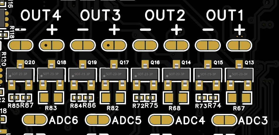
OUT jumpers

OUT [+] / [—] jumpers change the polarity of the output signal: [+] — the output supplies +12 V, [—] — it pulls the pin to ground.

Do not solder both jumpers on the same channel!

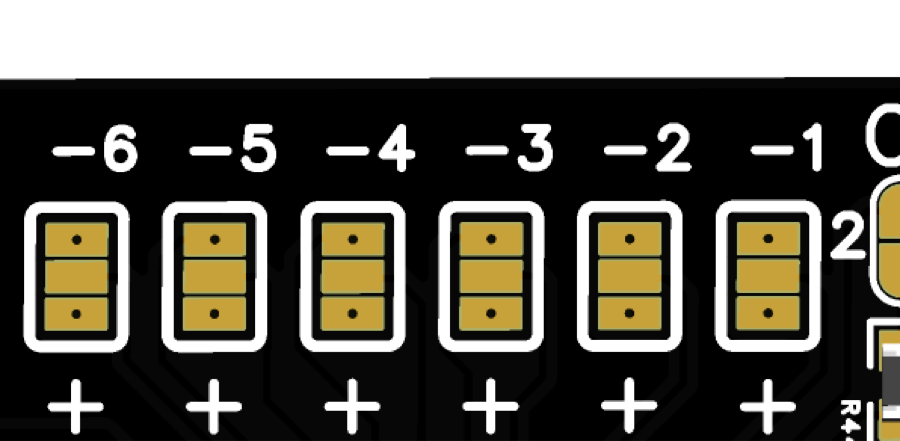
IN jumpers

IN [+] / [—] jumpers change the polarity of the input signal: [+] — the input triggers on +12 V, [—] — on a short to ground.

Output as input · ADCn OUTn

An output can work as an input: the “ADCn OUTn” jumper connects the pin to a 0…14 V voltage meter, with the OUTn [+] and OUTn [—] jumpers left open. Such a board is prepared at the factory for a specific adapter.

The other outputs work the same way: OUT2 — ADC4, OUT3 — ADC5, OUT4 — ADC6.

GoSwap · goswap.kz/catalog/u1-v5/en/ · +7 747 505 1212 4 / 6

CAPT / +5V jumper

Pin 11 works in one of two ways, chosen by a three-pad jumper on the bottom side of the board. CAPT is a frequency input: engine speed, vehicle speed. +5V is a 5 V output to power sensors. The middle pad is the pin itself: it is soldered either to the pad by the “+5V” label or to the other one. It is soldered at assembly for the specific adapter. The jumper is on boards from revision v5.1; v5 does not have it.

J0…J3 jumpers

What these jumpers switch on is set by the adapter firmware: for example, on fan adapters the fan type is chosen by soldering J1…J3. Which ones to solder is in your adapter’s manual. J0 appeared in revision v5: earlier boards have only J1…⁠J3.

GoSwap · goswap.kz/catalog/u1-v5/en/ · +7 747 505 1212 5 / 6

CAN termination jumper

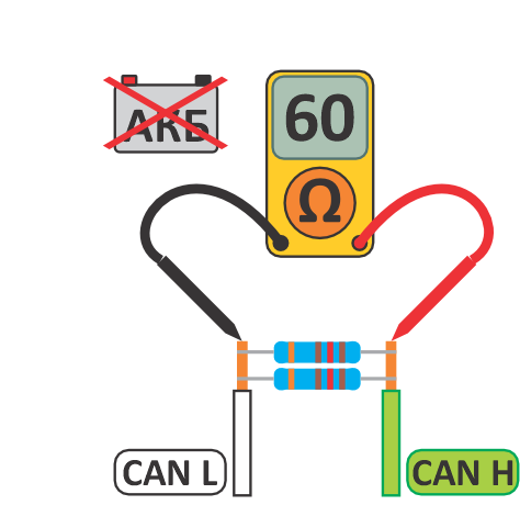
For proper CAN mode operation, the resistance between CAN H and CAN L wires must be 60 Ω. Measure resistance with the adapter connected and battery disconnected. The adapter has a built-in 120 Ω resistor — solder the CAN1 or CAN2 jumper if needed — for the bus the adapter is connected to.

Question about wiring? Call or message us on WhatsApp: +7 747 505 1212

GoSwap · goswap.kz/catalog/u1-v5/en/ · +7 747 505 1212 6 / 6