CAN adapter for the stock Land Rover Defender Puma 2007–2016 instrument cluster after a swap to an engine without CAN
Adapter for the stock Land Rover Defender 2.4 Puma (2007–2016) CAN instrument cluster after swapping in an engine without a CAN bus. Not suitable for models with an analog instrument cluster. The original engine control unit that fed the cluster is gone: the adapter reads RPM from the tachometer output of the engine control unit, coolant temperature from the stock sensor in parallel with the unit or from a separate sensor, and the Check Engine, glow plug, oil pressure and charge lamps from wires, and sends all of it to the cluster over CAN. The speedometer, odometer, fuel gauge and the other lamps still get their signals over wires. Set up in the GoSwap configurator from a phone over a USB cable: which temperature sensor is fitted and its calibration, tachometer pulses per revolution, the oil pressure sensor type and where the charge lamp comes from — the alternator or the vehicle voltage.
Optional: not needed if the charge lamp works by vehicle voltage. Active-low input — triggers when shorted to ground. Input polarity is set by a jumper.
The stock sensor stays in place, the wire runs in parallel with the engine control unit: Td5 — to pin C0158-7 of the unit, a Toyota engine — to pin THW. A separate Bosch sensor — to one of its terminals, the second terminal — to GND [12].
12GND
Black
GND — ground of a separate temperature sensor
Optional: connected only if a separate Bosch sensor is fitted — to its second terminal.
[—] — output switches to ground · [+] — input triggers from +12 V
Not used: 2, 4–11, 14, 16, 21, 23.
Connection order
1Connect ground GND[1] to the engine control unit ground and power +IGN[13] to +12 V from the ignition switch. With the stock temperature sensor the adapter ground is shared with the unit: Td5 — the unit ground, a Toyota engine — pin E1 of the unit; through another ground the temperature reading drifts.
2Connect the cluster bus: CAN H[15] and CAN L[3] — to CAN H and CAN L of the Defender instrument cluster.
3Tachometer TACH[22] — to the tachometer output of the engine control unit (Td5 — pin C0658-19).
4Temperature sensor TEMP[24]: the stock sensor stays in place, TEMP[24] goes to its wire at the unit, in parallel with the unit (Td5 — pin C0158-7, a Toyota engine — THW). A separate Bosch 0 281 002 209 sensor is for the adapter only: one terminal to TEMP[24], the other to GND[12], do not connect it to the unit.
5Engine lamps: CHECK[17] — to the malfunction lamp of the unit (Td5 — pin C0658-6), GLOW[18] — to the glow plug lamp of the unit (Td5 — pin C0658-30), OIL[20] — to the oil pressure sensor.
6Charge lamp from the alternator — D+[19] to the alternator D+ terminal. The cluster has no wired charge lamp, so the alternator needs its own excitation circuit: a lamp or a resistor from the ignition to D+. If the charge lamp works by vehicle voltage, D+[19] is not connected.
Jumpers
IN jumpers
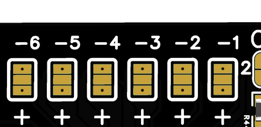
IN [+] / [—] jumpers change the polarity of the input signal: [+] — the input triggers on +12 V, [—] — on a short to ground.
From the factory all five inputs are soldered to negative: CHECK[17], GLOW[18], D+[19], OIL[20] and TACH[22] trigger when shorted to ground — nothing needs changing. TACH[22] is negative only, even if other units are connected to the wire.
TACHOILD+GLOWCHECK
Input jumper IN1 · connector pin 17
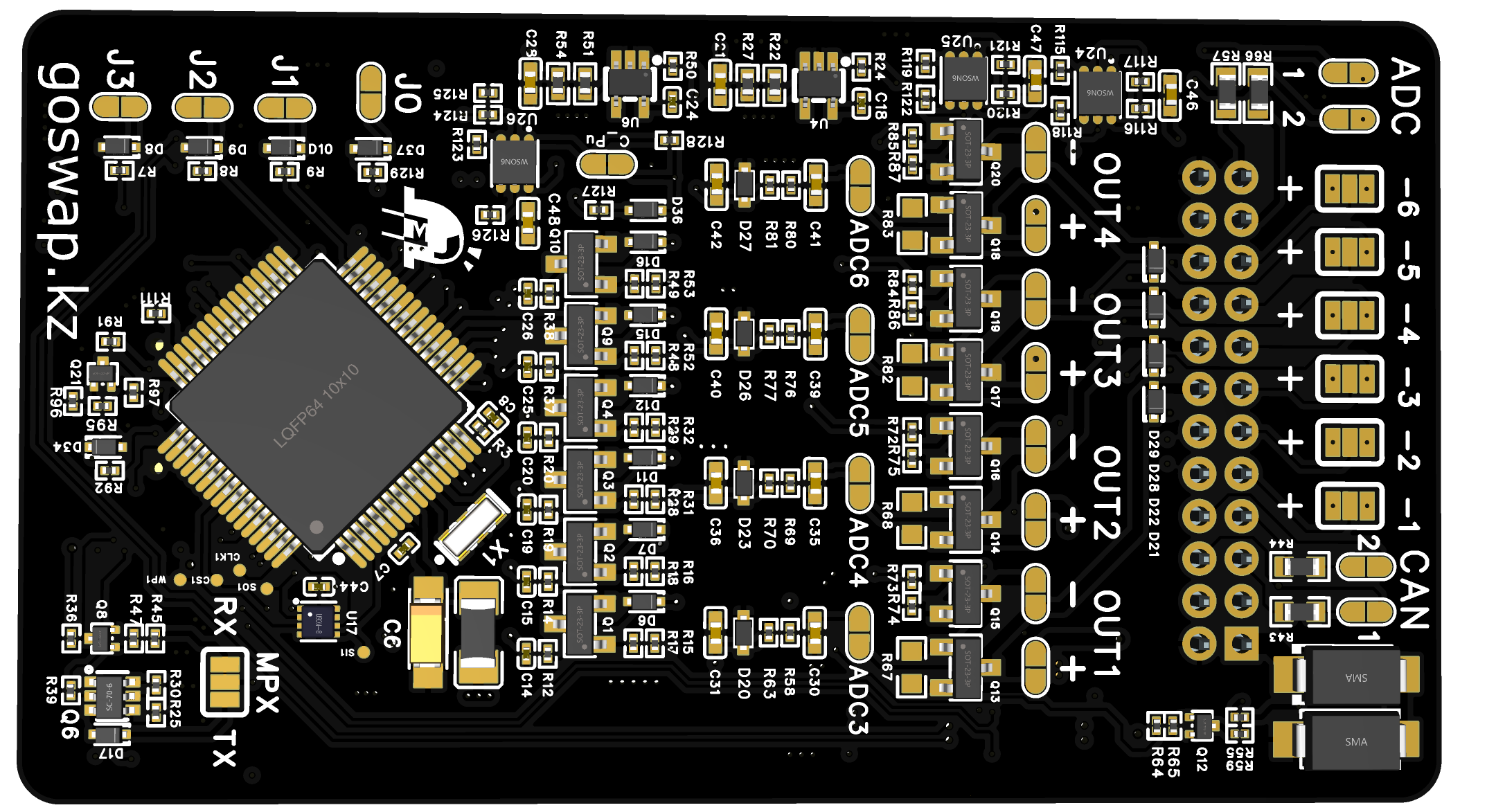
Tap a channel and [+] / [—] — the photo shows where to solder
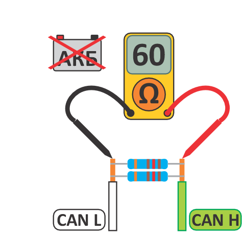
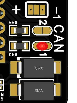
For proper CAN mode operation, the resistance between CAN H and CAN L wires must be 60 Ω. Measure resistance with the adapter connected and battery disconnected. The adapter has a built-in 120 Ω resistor — solder the CAN1 or CAN2 jumper if needed — for the bus the adapter is connected to.
From the factory the terminator is not soldered. The adapter connects to the Defender cluster bus — if the measurement shows 120 Ω, solder the CAN1 jumper.
The adapter is set up in the GoSwap app from a phone over a USB Type-C cable. Changes are sent to the adapter with the “APPLY” button at the bottom of the screen — the number on it shows how many settings have changed. The new value takes effect at once, no adapter restart needed.
1
Connect the phone.
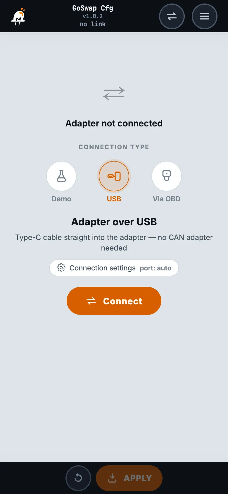
Install the GoSwap app — app page. Turn on the ignition, connect the phone and the adapter with a USB Type-C cable, choose “USB” in the app and tap “Connect”.
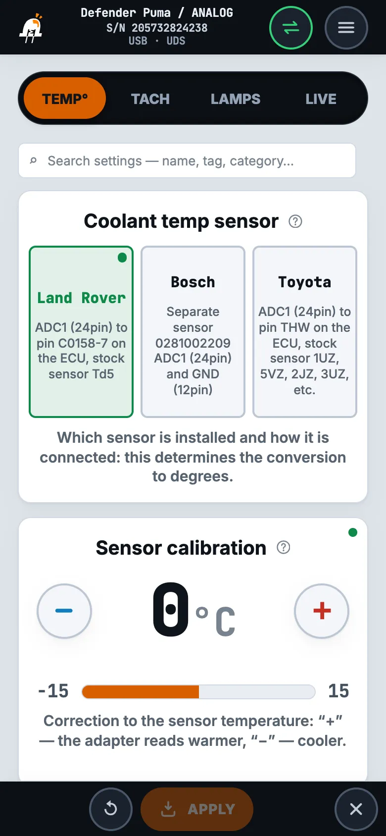
In “Coolant temp sensor” choose which sensor is fitted and how it is connected: “Land Rover” — the stock Td5 sensor in parallel with the unit, “Toyota” — the stock sensor of a Toyota engine in parallel with the unit, “Bosch” — a separate 0 281 002 209 sensor for the adapter only. Do not choose “Bosch” with the stock sensor: the engine control unit will see the engine colder than it is.
“Sensor calibration” — on a warm engine: compare the “Coolant temp” tile with the temperature the engine control unit shows in diagnostics. The tile shows less — increase the value by the difference, more — decrease it, then “APPLY”. The cluster needle moves together with the tile.
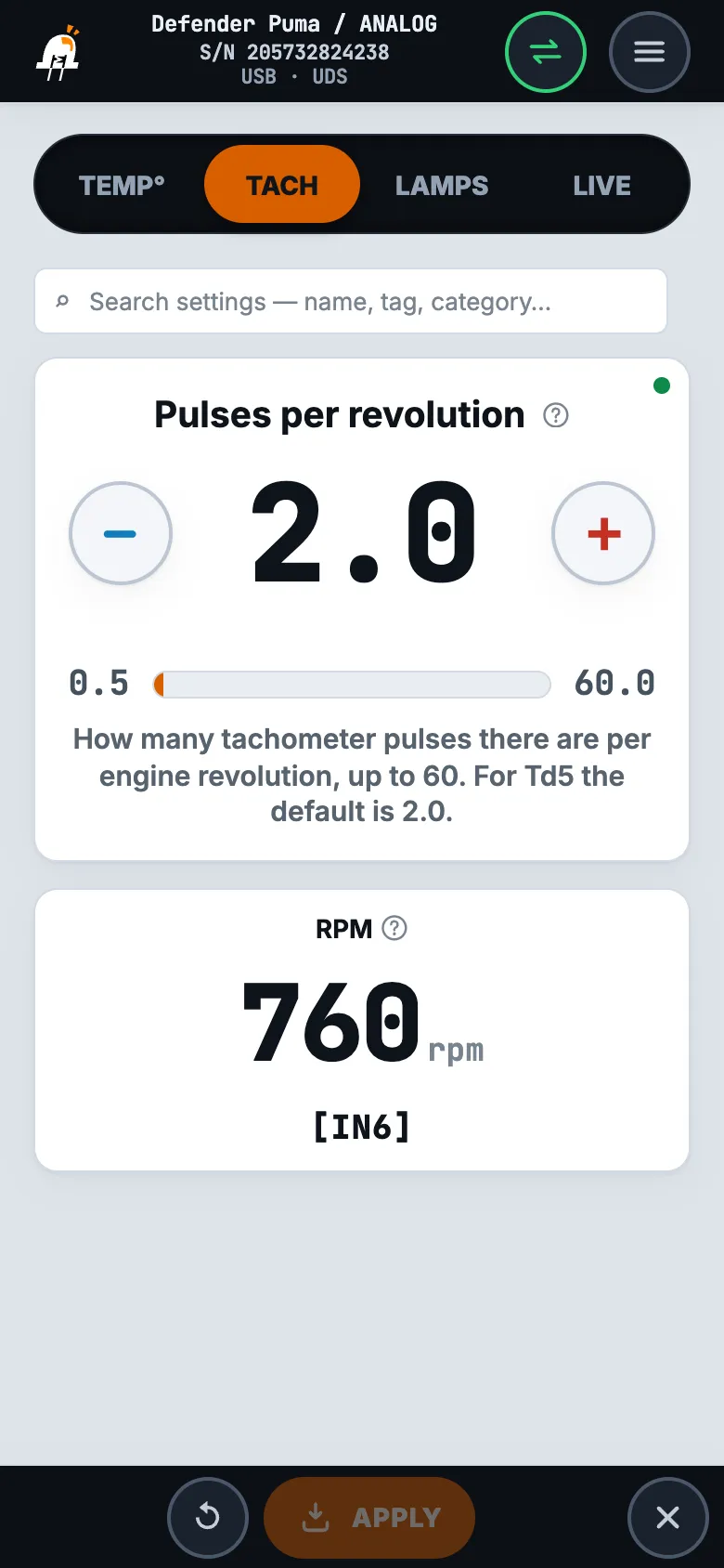
“Pulses per revolution” — how many tachometer pulses there are per engine revolution, 2.0 by default for Td5. At idle compare the “RPM” tile with the engine control unit RPM in diagnostics: the tile shows half — halve the value, double — double it. Then “APPLY” and check at different RPM.
“Oil pressure sensor”: almost all sensors are “Closed” — with no pressure the contact is closed to ground. Check: ignition on, engine stopped — the oil pressure lamp on the cluster is on, after starting it goes out. If it is the other way round — choose “Open”.
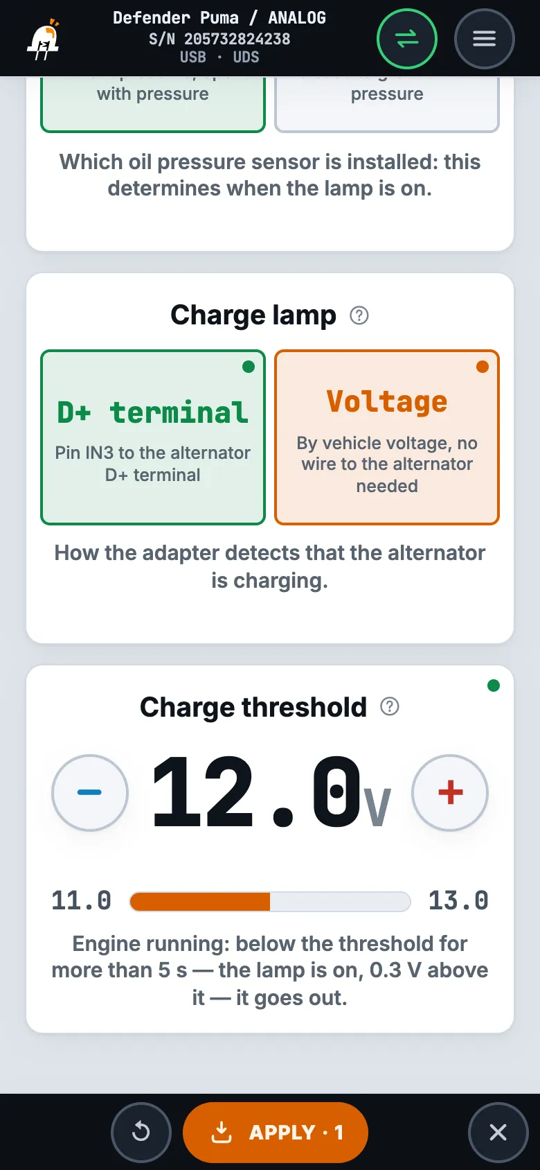
“Charge lamp”: “D+ terminal” — by the D+[19] wire from the alternator, “Voltage” — by vehicle voltage, no wire to the alternator needed.
“Charge threshold” — only for “Voltage”: with the engine running, voltage below the threshold for more than 5 seconds turns the lamp on, 0.3 V above the threshold turns it off; while the engine is not turning, the lamp is on. Start at 12.5 V and adjust by the “Voltage” tile at the top of the tab: with the engine running under load — headlights, fan — it should be at least 0.3 V above the threshold.
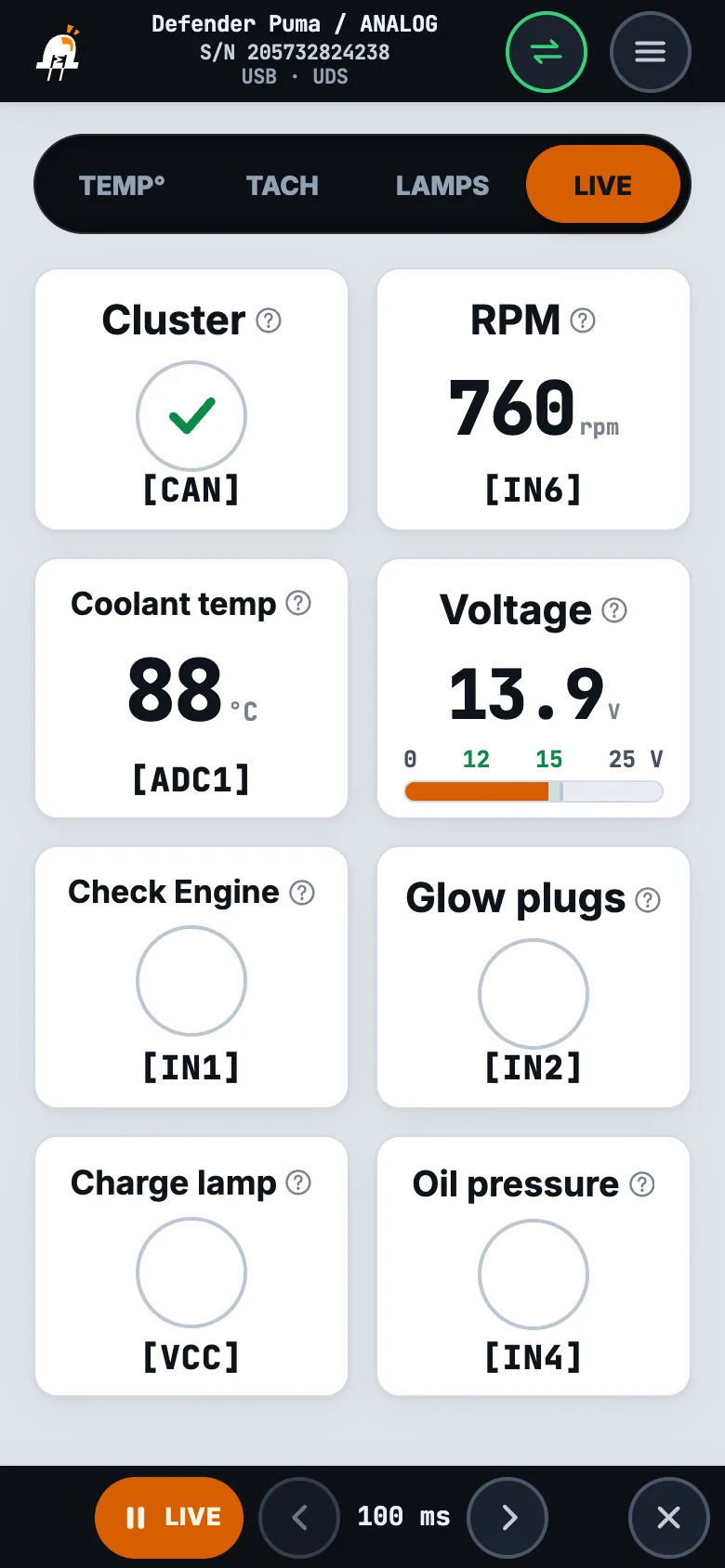
The tiles show what the adapter reads from the engine and sends to the cluster right now:
“Cluster” — a check mark: the cluster is talking over CAN. A cross — check the bus: CAN H[15] and CAN L[3] must not be swapped, resistance between them with the battery disconnected — 60 Ω.
“RPM” — from the tachometer TACH[22], the same as sent to the cluster. Zero with the engine running — check the TACH[22] wire; differs from diagnostics — adjust “Pulses per revolution” (step 3).
“Coolant temp” — temperature from the TEMP[24] sensor, with calibration applied: the cluster needle shows the same. If the sensor is open or shorted, the needle goes to the overheat zone.
“Voltage” — voltage at the adapter itself, normally 12–15 V. It also depends on the ground: lower than at the battery — check ground GND[1] and power +IGN[13].
“Check Engine”, “Glow plugs”, “Charge lamp” and “Oil pressure” — the circle lights up when the lamp is on in the cluster; the signals come from the CHECK[17], GLOW[18], D+[19] and OIL[20] wires. Ignition on, engine stopped — “Charge lamp” and “Oil pressure” are on, after starting they go out.
The red LED on the adapter is on, the cluster needles do not move
The cluster is silent — no CAN link. Check that CAN H[15] and CAN L[3] are not swapped; resistance between them with the battery disconnected — 60 Ω (CAN terminator); power +IGN[13] and ground GND[1]. In the app — the “Cluster” tile on the LIVE tab.
Tachometer
The tachometer reads more or less than it should
Adjust “Pulses per revolution” on the TACH tab: new value = current × “RPM” tile reading ÷ RPM in diagnostics (reads half — halve it). Check at different RPM — Setup, step 3.
The engine is running, but the tachometer needle is at zero
The blue LED on the adapter is off — the adapter does not see RPM. Most often the wire is taken from the wrong pin: TACH[22] goes to the tachometer output of the engine control unit (Td5 — pin C0658-19). The input jumper is “−” (Jumpers).
Temperature
The temperature needle shows overheat on a cold engine or minimum on a hot one
The orange LED flashes in series of 10 — the sensor is open or shorted, the needle goes to overheat: check the TEMP[24] wire. Not flashing — check the ground: with the stock sensor GND[1] goes to the engine control unit ground, with a separate Bosch sensor — GND[12]. And whether the sensor chosen on the TEMP° tab is the one fitted — Setup, step 2.
The cluster temperature differs from diagnostics by a few degrees
Match it with “Sensor calibration” on a warm engine — Setup, step 2. With the stock sensor the adapter ground GND[1] must be shared with the engine control unit: through another ground the reading drifts.
Lamps
The charge lamp is off with the ignition on and the engine stopped
Check the D+[19] wire to the alternator D+ terminal and the alternator excitation circuit — a lamp or a resistor from the ignition to D+. You can do without the wire to the alternator: on the LAMPS tab set “Charge lamp” to “Voltage”.
A cluster lamp comes on at the wrong time, or the wrong lamp comes on
Check on the LIVE tab: ignition on, engine stopped — short the lamp wire (CHECK[17], GLOW[18], OIL[20]) to ground, its tile and the cluster lamp light up. Another one lit up — the wires are swapped. The oil pressure lamp is on with the engine running and off with it stopped — the sensor is normally open: “Oil pressure sensor” — “Open”, Setup, step 4.
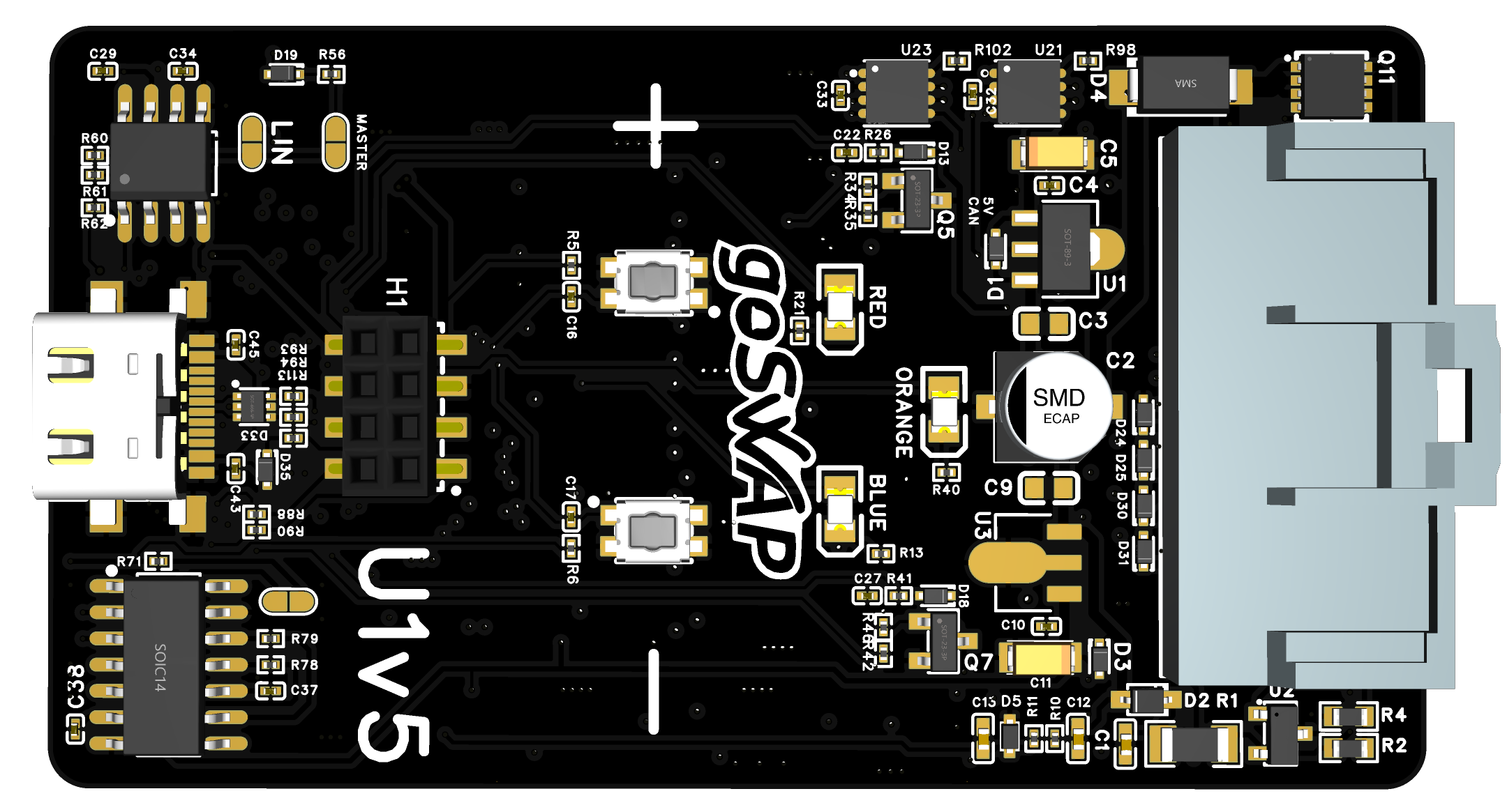
Board
Hover or tap an element to see its function
On — the cluster is silent, no CAN link: check the CAN H [15] and CAN L [3] wires. Off — the cluster is talking. Without the cluster, on a USB cable alone, red is on — this is expected.
Off — the temperature sensor is fine. Flashes 10 times in a row — the sensor is open or shorted: check the TEMP [24] wire.
On — the adapter sees RPM: the engine is turning.
USB Type-C — for a phone with the GoSwap app: setup and firmware update. No CAN interface is needed.
Polarity of inputs IN1…IN6 — one jumper per input: [+] or [—].
Built-in 120 Ω resistor for the CAN1 or CAN2 bus. When to solder it — see “Jumpers”.
During a firmware update red, orange and blue light up in turn, in a circle.