8th-gen Toyota Hilux Revo (N80, from 2015) after a 3UZ-FE V8 conversion with the 6AT automatic: the adapter runs the stock ABS and instrument cluster; setup in the app.
Adapter for swapping a 3UZ-FE V8 with the 6AT automatic into a Toyota Hilux Revo (N120, from 2015). After the swap the stock Hilux ABS unit and instrument cluster do not understand the new engine: stability control switches off with an error, the cluster shows no RPM or temperature. The adapter sends them the engine and transmission data the way the original Hilux engine did — the ABS, the cluster and the lamps work like stock. Set up in the GoSwap app from a phone over a USB Type-C cable. If the car left the factory with a manual transmission, its stock cluster must be reflashed to show the gears — GoSwap does this.
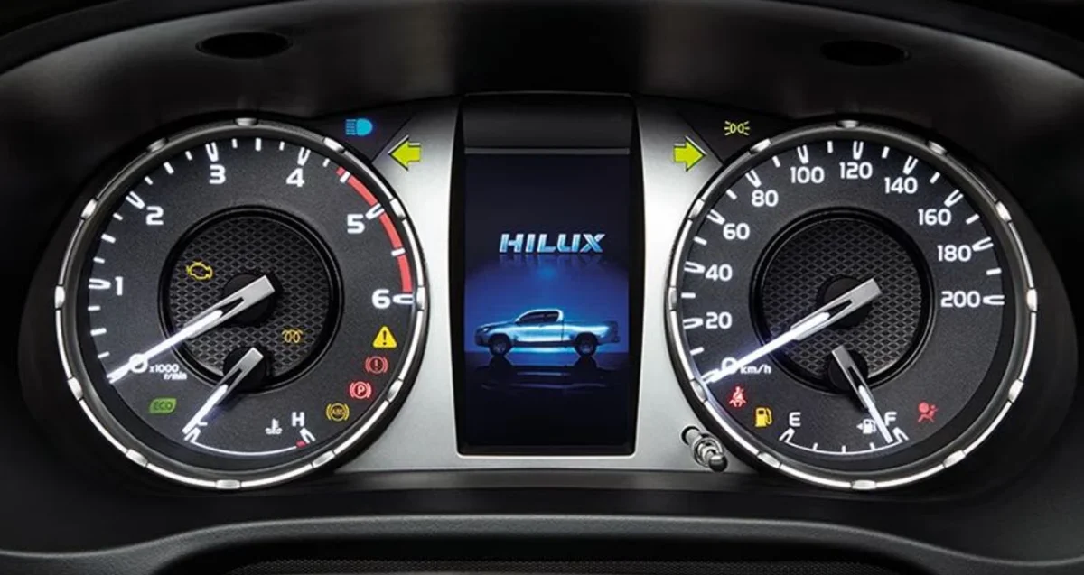
Stock Hilux Revo instrument cluster with a color display — the adapter works with it
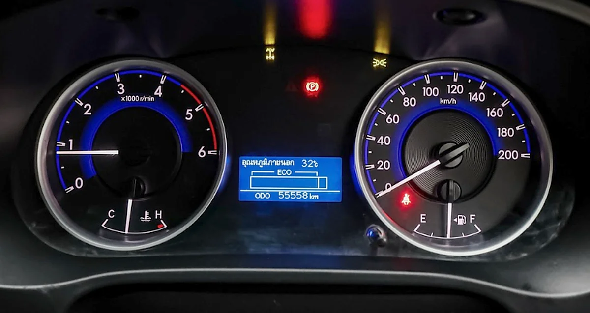
Hilux Revo instrument cluster in the base trim — the adapter works with it too
Toyota Hilux Revo (N120, from 2015) — the car the adapter is made for
Connection
12 11 10 9 8 7 6 5 4 3 2 1
NEOCAN2LCAN1LGND
SNWPWRACOILGENCHECKCAN2HCAN1H+IGN
24 23 22 21 20 19 18 17 16 15 14 13
13+IGN
Red
+IGN — +12 V from the ignition switch — positive with the ignition on
1GND
Black
GND — to body ground
3CAN1 L
White
CAN1 L — to CAN L of the body bus — the wire that went to the removed stock GD / 2TR engine control unit
15CAN1 H
Green
CAN1 H — to CAN H of the body bus — the wire that went to the removed stock GD / 2TR engine control unit
4CAN2 L
White
CAN2 L — to CAN L of the 3UZ engine control unit — pin A24
16CAN2 H
Orange
CAN2 H — to CAN H of the 3UZ engine control unit — pin A25
5PWM1[—]
Light gray
NEO — to the NEO wire of the start system — on cars with a push-button start
Optional: not connected without a push-button start. Low-side output.
17IN1[—]
Yellow
CHECK — to the W terminal of the 3UZ engine control unit (B8) — Check Engine lamp
Active-low input — triggers when shorted to ground. The cluster gets the Check Engine lamp only from this wire. Input polarity is set by a jumper.
18IN2[—]
Pink
GEN — to the alternator L terminal — charge lamp
Active-low input — triggers when shorted to ground: while the alternator is not charging, the L terminal is pulled to ground. The wire is in the harness from the factory; connect it only if IN2 is selected in “Charge lamp source” in the app. Input polarity is set by a jumper.
19IN3[—]
Gray
OIL — to the oil pressure sensor — pin E5 (MOPS) of the 3UZ control unit
Active-low input — the sensor shorts the wire to ground when there is no pressure. The wire is in the harness from the factory; connect it only if IN3 is selected in “Oil lamp source” in the app. Input polarity is set by a jumper.
20IN4[—]
Blue
AC — to pin AC1 of the climate control unit — the wire that went to the stock engine control unit
Active-low input — ground on the wire: the air conditioning is on, the adapter passes the request to the 3UZ engine control unit. Input polarity is set by a jumper.
21IN5[—]
Brown
PWR — to the POWER mode button — the stock one or your own non-latching button
Optional. Active-low input — the button shorts the wire to ground. A non-latching button, like the stock one. Input polarity is set by a jumper.
22IN6[—]
Purple
SNW — to the SNOW mode button — the stock one or your own non-latching button
Optional. Active-low input — a press shorts the wire to ground. Your own button must be non-latching: the 3UZ unit switches SNOW mode on a press. Input polarity is set by a jumper.
[—] — output switches to ground · [+] — input triggers from +12 V
Not used: 2, 6–12, 14, 23, 24.
Wire colors may differ between batches — go by the pin number.
Connection order
1Connect ground GND[1] to the body and power +IGN[13] — to +12 V from the ignition switch.
2Connect the buses. Body bus CAN1 H[15] and CAN1 L[3] — to the CAN H and CAN L wires that went to the removed stock GD or 2TR engine control unit, not to the OBD connector: the ABS unit and the instrument cluster are on this bus. Engine bus CAN2 H[16] and CAN2 L[4] — to pins A25 (CAN H) and A24 (CAN L) of the 3UZ control unit. Unit pin numbers here and below are from the 3UZ 6AT ECU pinout. A separate OBD connector for the 3UZ unit is not needed: the adapter passes diagnostics through — a scan tool in the stock OBD connector sees the 3UZ engine unit and the transmission as in the original car, reads and clears fault codes, shows live data. If the 3UZ unit needs flashing, we recommend doing it on the bench.
3The adapter does not pass the speed signal: the 3UZ unit gets it over a separate wire from the Hilux instrument cluster — connect this wire to pin SPD (A22) of the 3UZ unit, or feed the signal through the Divider from the transmission output shaft sensor (the Divider is not included). Without the speed signal the 3UZ unit does not know the vehicle speed.
4Lamps from the engine: Check Engine CHECK[17] — to the W terminal (B8) of the 3UZ control unit. Charge GEN[18] — to the alternator L terminal, oil pressure OIL[19] — to the oil pressure sensor, pin E5 (MOPS) of the 3UZ unit (3UZ 6AT ECU pinout): the sensor shorts the wire to ground when there is no pressure. GEN[18] and OIL[19] are in the harness from the factory; connect them only if source IN2 or IN3 is selected for the lamp in the app — Setup.
5A/C request AC[20] — to pin AC1 of the climate control unit: this wire went to the stock engine control unit.
6Optional inputs. Transmission modes: PWR[21] and SNW[22] — to the stock POWER and SNOW buttons if the car was an automatic (their wires went to the stock engine control unit), or to your own — both non-latching, like the stock ones: a press switches the mode. If the car has a push-button start — NEO[5] to the NEO wire of the start system; without a push-button start NEO[5] is not connected.
Jumpers
IN jumpers
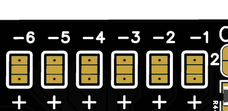
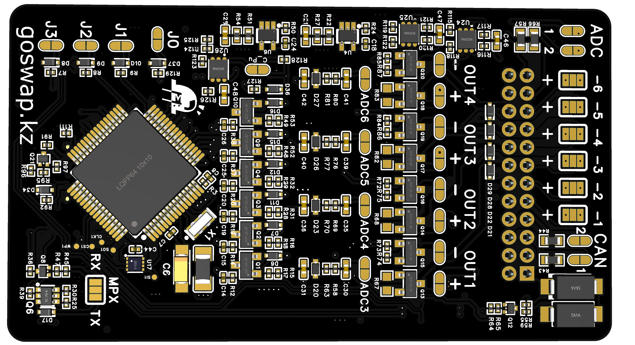
IN [+] / [—] jumpers change the polarity of the input signal: [+] — the input triggers on +12 V, [—] — on a short to ground.
From the factory all six inputs are soldered active-low: CHECK[17], GEN[18], OIL[19], AC[20], PWR[21] and SNW[22] trigger when shorted to ground — nothing needs changing.
SNWPWRACOILGENCHECK
Input jumper IN1 · connector pin 17
Tap a channel and [+] / [—] — the photo shows where to solder
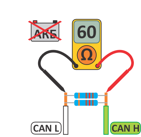
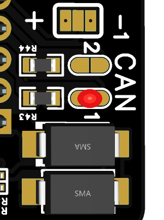
For proper CAN mode operation, the resistance between CAN H and CAN L wires must be 60 Ω. Measure resistance with the adapter connected and battery disconnected. The adapter has a built-in 120 Ω resistor — solder the CAN1 or CAN2 jumper if needed — for the bus the adapter is connected to.
From the factory the terminators are not soldered. Measure the resistance between CAN H and CAN L of each bus with the adapter connected and the battery disconnected: normal is 60 Ω. If a bus shows 120 Ω — solder the jumper of that bus: CAN1 — body bus, CAN2 — engine bus.
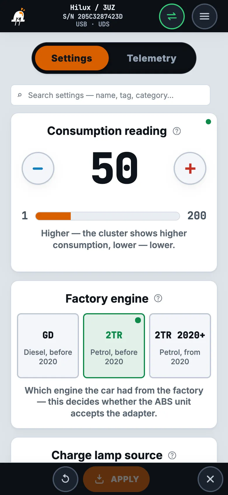
The adapter is set up in the GoSwap app from a phone over a USB Type-C cable. There are four settings, all on the “Settings” tab. Changes are sent to the adapter with the “APPLY” button at the bottom of the screen — the number on it shows how many settings have changed. A new value takes effect at once, the adapter does not need a restart.
1
Connect the phone.
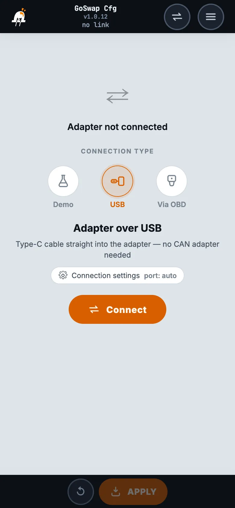
Install the GoSwap app — app page. Turn on the ignition, connect the phone and the adapter with a USB Type-C cable, choose “USB” in the app and tap “Connect”.
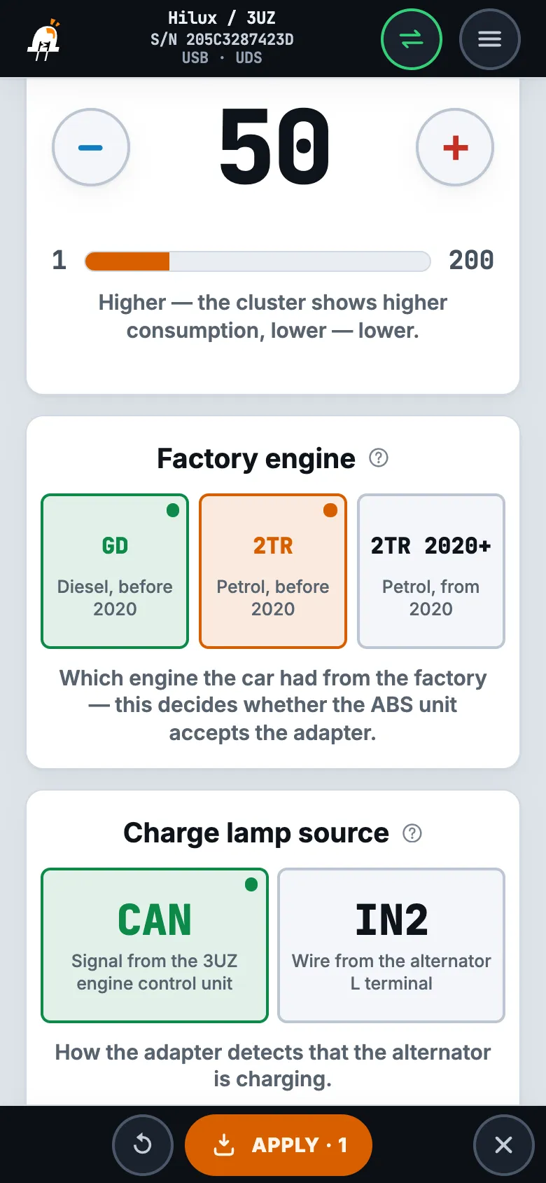
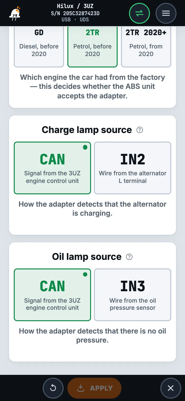
“Factory engine” — the engine the car had from the factory, not the 3UZ: “GD” — diesel before 2020, “2TR” — petrol before 2020, “2TR 2020+” — petrol from 2020. It decides whether the ABS unit accepts the adapter. Choose it and tap “APPLY”, then calibrate the ABS unit — the next step.
The ABS unit memorizes the engine it sees on the bus. After the adapter is installed, the unit is calibrated once with a scan tool (Launch or Techstream), the ABS / VSC section. Until the ABS unit is calibrated, VSC stability control and TRC traction control are off.
The adapter is connected and talking to the engine control unit and the ABS unit: on the “Telemetry” tab the “Engine” and “ABS” tiles show check marks. Ignition on, do not start the engine.
Make sure the 3UZ engine control unit has no faults: read its codes with a scan tool through the stock OBD connector and fix them before calibration.
Steering wheel straight, lever in P or N, parking brake on, the car stands on level ground (slope under 1 %) and does not move for at least 5 seconds. Without P or N the ABS unit will not accept the calibration.
In the scan tool select the car manually — Toyota Hilux, then the ABS / VSC section: Reset Memory — erases the previous calibration, then Test Mode and Signal Check — zero point calibration: the ABS unit memorizes the engine anew.
Clear the codes and read them again — no codes. Turn the ignition off and on: error C1203 has not come back.
If another engine was connected to the bus, for example the stock engine control unit put back, calibrate again.
C1203 persists after calibration — choose another “Factory engine” value (step 2) and calibrate again.
4
Lamps — “Charge lamp source” and “Oil lamp source”.
Where the adapter takes the lamps from: “CAN” — the signal from the 3UZ engine control unit, “IN2” — the GEN[18] wire from the alternator L terminal, “IN3” — the OIL[19] wire from the oil pressure sensor. The default is CAN.
Check on the spot: choose CAN and turn on the ignition without starting the engine. On the “Telemetry” tab the “Charge lamp” and “Oil pressure” tiles are lit. If one is not lit, that signal is not arriving from the engine control unit: choose IN2 or IN3 for it, then “APPLY”.
While the engine is stopped, the charge lamp on the cluster is always on, like the stock one. The oil pressure lamp lights only from the selected signal, whether the engine is running or not.
The feature is experimental. “Consumption reading” raises or lowers the consumption on the trip computer for your car: more — higher, less — lower. The scale is arbitrary: 50 is the factory setting, consumption without correction.
Adjust only while driving, at a steady speed. Most accurate is to compare the trip computer's average consumption with the consumption measured from a full tank to a full tank: reading too high — decrease, too low — increase, then “APPLY”. When parked, the trip computer shows the end of the scale at any setting — it divides consumption by speed.
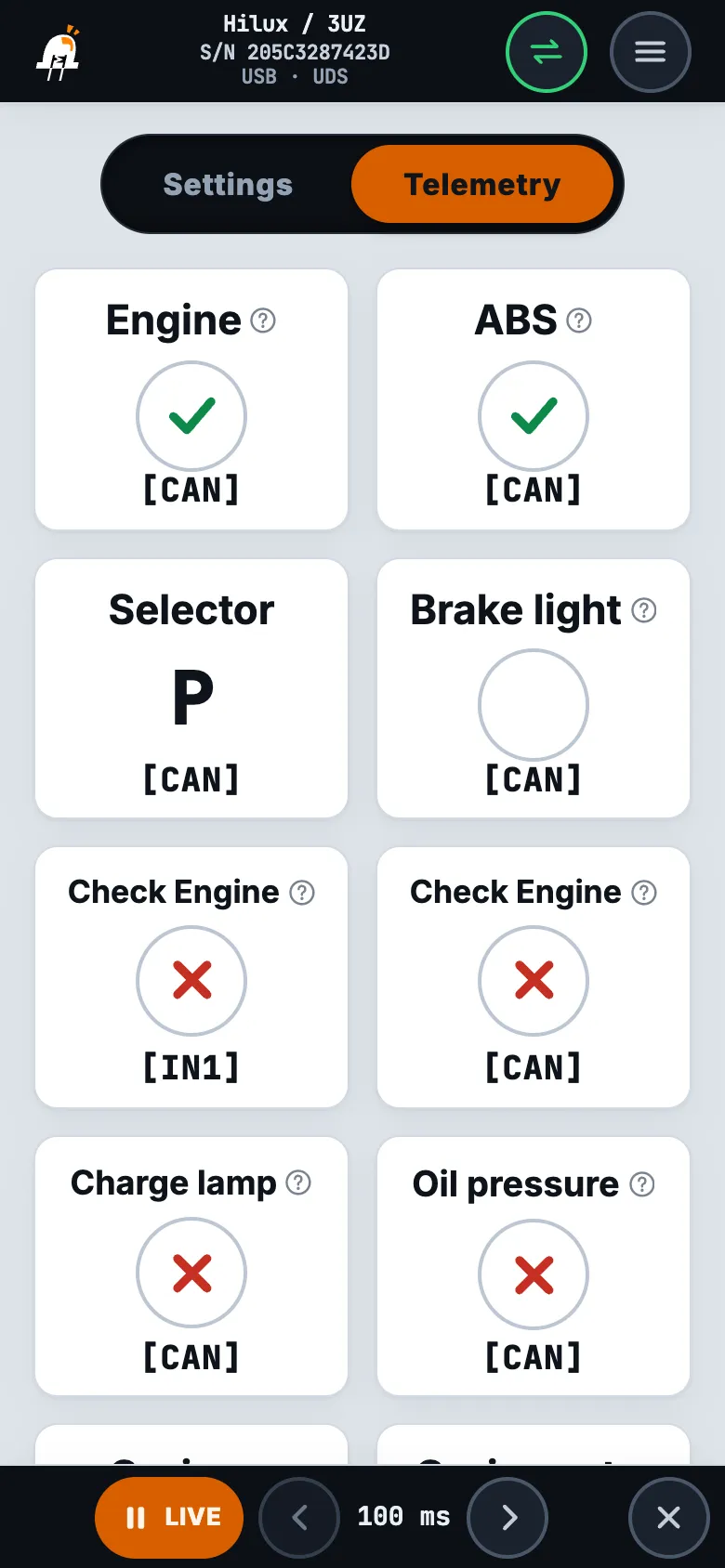
The tiles show what the adapter is receiving from the engine control unit, the ABS unit and the wires right now. Most convenient — with the ignition on before starting the engine:
“Engine” and “ABS” — the link with the 3UZ control unit over the CAN2 H[16] / CAN2 L[4] bus and with the ABS unit over the CAN1 H[15] / CAN1 L[3] bus: a check mark — the link is up. A cross — check the wires of that bus: are CAN H and CAN L swapped, is the bus connected to the other adapter input; resistance between CAN H and CAN L with the battery disconnected — 60 Ω.
“Selector” — lever position: P, R, N, D, in S mode — with the gear number (S1…S6). “Brake light” — the brake pedal as reported by the engine control unit: the circle lights up when the pedal is pressed.
“Check Engine” — two tiles: from the CHECK[17] wire (IN1 in the app) and over CAN from the engine control unit. With the ignition on before starting both are lit — this is the lamp check; after starting they go out. The cluster lamp comes only from the CHECK[17] wire.
“Charge lamp” and “Oil pressure” — from the source chosen in step 4: ignition on, engine stopped — the circle is lit; after starting it goes out.
“Cruise” and “Cruise set”, “POWER” and “SNOW” — as reported by the engine control unit: the circle lights up when cruise is on and the speed is set, when the mode is on. On the cluster POWER mode is the PWR indicator, SNOW — ECO.
“Voltage” — voltage at the adapter itself, normally 12–15 V. It also depends on the ground: lower than at the battery — check ground GND[1] and power +IGN[13].
“A/C request”, “POWER button” and “SNOW button” — signals on the AC[20], PWR[21] and SNW[22] wires: the tile lights up when the wire is grounded — the air conditioning is on, the button is pressed. A non-latching button lights up only while it is held; whether the mode is on is shown by the “POWER” and “SNOW” tiles.
The RPM and temperature needles are at zero, the orange LED on the adapter flashes and the red one is on
The adapter does not see the 3UZ control unit, and without it the adapter sends nothing to the car. Check the engine bus CAN2 H[16] and CAN2 L[4]: are the wires swapped, are they connected to CAN1 instead of CAN2; resistance between CAN H and CAN L with the battery disconnected — 60 Ω (CAN terminator). Also check power +IGN[13] and ground GND[1]. In the app — the “Engine” tile on the “Telemetry” tab.
The orange LED on the adapter flashes and the blue one is on
The adapter does not see the ABS unit on the body bus. Check CAN1 H[15] and CAN1 L[3]: are they connected to the wires of the removed stock engine control unit, are they swapped, are they connected to CAN2 instead of CAN1; resistance between CAN H and CAN L with the battery disconnected — 60 Ω (CAN terminator). In the app — the “ABS” tile on the “Telemetry” tab.
ABS unit
After the swap the ABS unit keeps error C1203
The ABS unit has to be calibrated with a scan tool — following the Setup steps: no faults in the 3UZ unit, the adapter is online, ignition on without starting, lever in P or N, the car selected manually in the scan tool — Toyota Hilux, Reset Memory, then Test Mode and Signal Check, clear the codes. Without P or N the calibration does not go through; after another engine on the bus — calibrate again. Check “Factory engine”: the selected engine is the one the car had from the factory, not the 3UZ. C1203 persists after calibration — choose another value and calibrate again.
Instrument cluster
The cluster does not show the lever position and gear
If the car left the factory with a manual transmission, its stock cluster does not show the automatic's lever position and gear until it is reflashed. GoSwap reflashes the cluster — contact us. What the adapter receives from the transmission is shown in the app on the “Selector” tile of the “Telemetry” tab.
Lamps
The oil pressure lamp on the cluster is off with the ignition on and the engine stopped
The lamp lights only from the selected signal. Look at the “Oil pressure” tile on the “Telemetry” tab: ignition on, engine stopped — it should be lit. Not lit with the CAN source — the engine control unit does not send this signal: choose IN3 in “Oil lamp source” and check the OIL[19] wire to the oil pressure sensor — Setup.
The charge lamp on the cluster does not go out after starting
Look at the “Charge lamp” tile on the “Telemetry” tab: after starting it goes out when the alternator is charging. Lit with the IN2 source — check the GEN[18] wire to the alternator L terminal and the alternator itself; with the CAN source the charging signal comes from the engine control unit. While the engine is stopped, the charge lamp on the cluster is always on, like the stock one.
Check Engine on the cluster does not light up with the ignition on
The cluster gets the Check Engine lamp only from the CHECK[17] wire: check that it is connected to the W terminal of the 3UZ control unit and the input jumper is “−” (Jumpers). With the ignition on before starting, the “Check Engine” tile from the wire on the “Telemetry” tab is lit.
Transmission modes
POWER mode turned off by itself
That is how it should be: POWER mode turns off when the ignition is switched off and when SNOW is pressed — turn it on again with the POWER button. Your own button must be non-latching: with a latching one the mode switches only on every other press. The press shows on the “POWER button” tile of the “Telemetry” tab, the mode itself on the “POWER” tile.
Fuel consumption
When parked, the trip computer shows huge consumption
That is expected: the trip computer divides consumption by speed and, when parked, shows the end of the scale at any setting. Check consumption only while driving.
While driving, the trip computer consumption is higher or lower than the real one
Adjust “Consumption reading” at a steady speed: too high — decrease the value, too low — increase it — Setup. The feature is experimental.
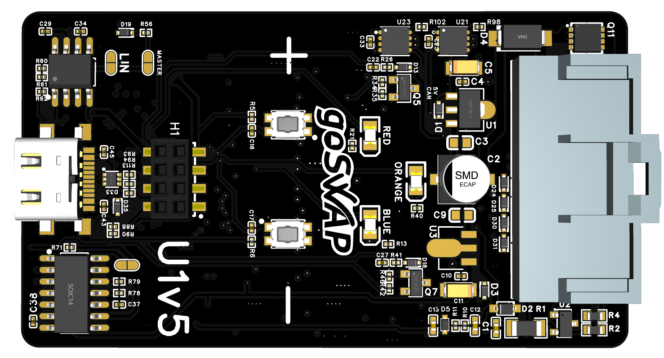
Board
Hover or tap an element to see its function
On while orange flashes — no link with the 3UZ engine control unit: check the CAN2 H [16] and CAN2 L [4] wires.
Off — the 3UZ engine control unit and the ABS unit are online. Flashes in series of 10 — no link: red or blue shows with which unit. While there is no link with the engine control unit, the adapter sends nothing to the car.
On while orange flashes — no link with the ABS unit: check the CAN1 H [15] and CAN1 L [3] wires.
USB Type-C — for a phone with the GoSwap app: setup, firmware update, CAN bus recording for support. No CAN interface is needed.
Polarity of inputs IN1…IN6 — one jumper per input: [+] or [—].
Built-in 120 Ω resistor for the CAN1 or CAN2 bus. When to solder it — see “Jumpers”.
Powered only from the USB cable, without the car, red and blue are on and orange flashes — that is expected: there are no units on the buses. The PWM1 LED is yellow, on v5.1 boards: it flashes with the NEO signal and lights up only if the start system side has a pull-up. During a firmware update red, orange and blue light up in turn, in a circle.