

Speedometer / Tachometer "Divider" Adapter

Also in: Swap adapters

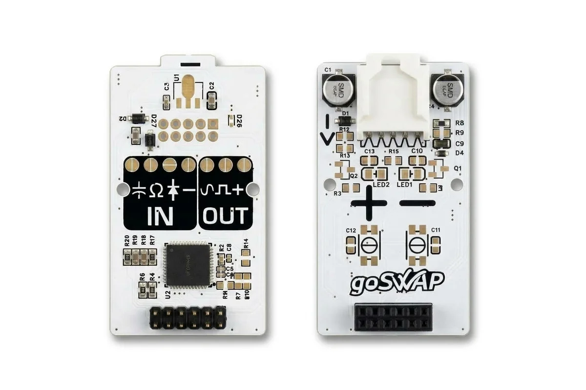
The adapter corrects tachometer and speedometer pulse signals in vehicles with a 12 V supply. Three operating modes: division, multiplication and generation. Every adapter goes through automated testing after assembly.

Download PDF

Connection

5 4 3 2 1
10 9 8 7 6
1 Red [+12V] — +12V from ignition Power
2 Black [GND] — ground Power
4 White [OUT] — output signal to the dashboard Output
5 Green [IN] — input signal from the sensor or ECU Input

Not used: 3, 6–10.

Modes

  1. Division1 blink

    The needle reads higher than actual: more pulses arrive than the dashboard expects. The adapter divides the frequency.

  2. Multiplication2 blinks

    The needle reads lower or does not rise: fewer pulses arrive than the dashboard expects. The adapter multiplies the frequency.

  3. Generation3 blinks

    The adapter outputs a signal by itself, no input needed — to check the dashboard and the wiring.

Default

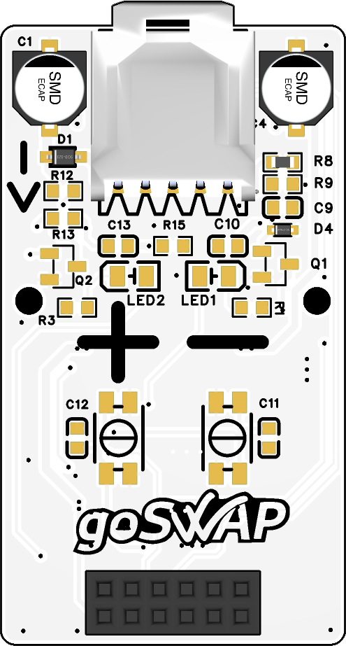
The adapter ships in Generation mode and outputs a 100 Hz signal; both LEDs are on — red and blue. Use the (+) or (−) buttons to change the frequency. This is used to check the dashboard, the power connection and the output signal.

Mode selection

  1. 1Disconnect power.
  2. 2Hold both buttons (+) and (−).
  3. 3Apply power while still holding the buttons.
  4. 4Release the buttons.
  5. 5The red LED shows the selected mode with short blinks: 1 — division, 2 — multiplication, 3 — generation.
  6. 6Select the desired mode with the (+) or (−) button.
  7. 7To save the selected mode, disconnect power.

Setup

Speedometer from output shaft sensor SP2+

  1. 1Power the adapter according to the diagram: +12V — from ignition, GND — ground.
  2. 2Connect the output signal OUT to the speedometer wire on the dashboard.
  3. 3Turn on the ignition to verify the connection: the speedometer needle should rise and stay at one position.
  4. 4Use the (+) or (−) buttons to change the generated frequency.
  5. 5Connect the input signal IN to the SP2+ pin of the transmission output shaft sensor.
  6. 6Select Division mode.
  7. 7While driving, use the (+) or (−) buttons to adjust the speedometer reading against GPS. Short press — fine adjustment; the longer you hold the button, the larger the step.
  8. 8The blue LED blinks together with the output signal.

Wait at least 10 seconds before disconnecting power.
Tachometer

  1. 1Power the adapter according to the diagram: +12V — from ignition, GND — ground.
  2. 2Connect the output signal OUT to the tachometer wire on the dashboard.
  3. 3Turn on the ignition to verify the connection: the tachometer needle should rise and stay at one position.
  4. 4Use the (+) or (−) buttons to change the generated frequency.
  5. 5Connect the input signal IN to the tachometer signal from the ECU or the ignition module.
  6. 6Select Division or Multiplication mode: if the tachometer reads higher than actual — division, lower — multiplication.
  7. 7Start the engine.
  8. 8Connect a diagnostic scanner and display the engine RPM.
  9. 9Use the (+) or (−) buttons to adjust the tachometer reading. Short press — fine adjustment; the longer you hold the button, the larger the step.
  10. 10The blue LED blinks together with the output signal.
  11. 11Verify the readings at different engine RPMs.

Wait at least 10 seconds before disconnecting power.
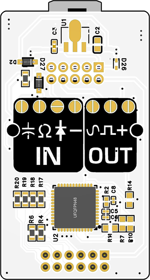
Board and jumpers

Hover or tap an element to see its function

Делилка — верх
Делилка — низ
Red LED
Blue LED
+ button
− button
Programming connector
Main connector
IN jumper
OUT jumper
IN — Capacitor
IN — Resistance
IN — Diode
IN — Minus
OUT — Sine
OUT — Square wave
OUT — Plus

Buttons

  • (+)Increase frequency / adjust reading. Short press — fine adjustment; the longer you hold the button, the larger the step.
  • (−)Decrease frequency / adjust reading. Short press — fine adjustment; the longer you hold the button, the larger the step.

Jumpers

Solder pads on the underside of the board. Two are soldered at the factory: OUT «square» and OUT «+». Nothing is soldered on the input — the input is «positive».

Input — how the adapter receives the signal

  • IN — capacitor: smooths the input signal. Used when the signal is noisy. Frequent pulses may be cut off with it.
  • IN — resistor (Ω): lowers the input resistance. Used when the signal source is weak.
  • IN — diode: the input accepts a signal of both polarities, not only positive. Used for a bipolar signal (sine).
  • IN — minus: pulls the input up to plus. Used for sensors that switch the signal to ground (open collector, reed switch). Without the jumper the input expects «positive» pulses.

Output — what signal the adapter sends

  • OUT — square: rectangular unipolar signal. Suits most dashboards and ECUs with a Hall sensor. Soldered at the factory.
  • OUT — sine: a signal without a DC component, for inputs designed for an inductive sensor: Nissan, Mazda, Subaru dashboards, crankshaft and camshaft sensor emulation. Solder together with «+». Do not solder with «square» — remove it.
  • OUT — plus (+): pulls the output up to the supply — the receiver gets a signal at vehicle voltage level. Soldered at the factory. Without it the output only switches to ground (open collector).

Question about wiring?

Outside working hours

We’re available Mon–Fri, 12:00 to 17:00 Almaty time. Message us on WhatsApp — we’ll reply as soon as we’re back at work.

Message on WhatsApp Call anyway